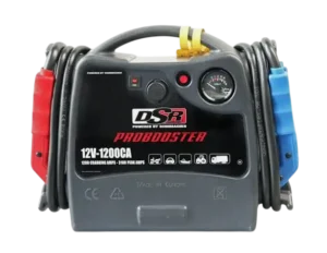
| Field | Details |
| Document Title | DSR101 Booster Owner’s Manual |
| Document Type | Owner’s Manual |
| Brand Name | DSR (Powered by Schumacher) |
| Product Name | ProBooster |
| Model Number(s) | DSR101 |
| PDF File Size | 370 KB |
| Number of Pages | 32 |
| Languages | English, Spanish, French |
Schumacher DSR ProBooster DSR101
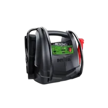
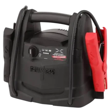
The DSR ProBooster DSR101, powered by Schumacher Electric Corporation, is a professional 12V battery booster designed for jump-starting vehicles with lead-acid batteries. It delivers 3200 peak amps, 560 cranking amps, and 345 cold cranking amps from an internal 12V, 32Ah maintenance-free AGM lead-acid battery.
The DSR101 also functions as a portable 12V DC power source for compatible electrical accessories. It features heavy-duty battery clamps, a built-in voltmeter, circuit breaker protection, and an auxiliary charging connection.
The booster includes an SC2DSR automatic battery charger for charging and maintaining its internal battery. The charger supports automatic charging, desulfation, and battery maintenance, with LED indicators showing power, charging progress, and battery conditions.
The DSR101 owner’s manual provides instructions for preparing the booster, charging its internal battery, connecting the clamps, jump-starting vehicles, operating 12V accessories, replacing the internal fuse, maintaining the battery, and troubleshooting common problems.
Product Features
The DSR ProBooster DSR101 includes the following features:
- 3200 peak amp jump-starting capability.
- 560 cranking amps.
- 345 cold cranking amps.
- Maintenance-free 12V AGM lead-acid internal battery.
- 32Ah battery capacity.
- Heavy-duty battery clamps.
- Red positive and blue negative clamps.
- 61-inch jumper cables with 50 mm² conductor size.
- Built-in analog voltmeter.
- Voltmeter push button.
- 12V DC accessory power outlet.
- Circuit breaker protection for the DC power outlet.
- Internal heavy-duty 300A AMG fuse.
- Auxiliary charging port.
- SC2DSR automatic battery charger.
- Automatic charging and Maintain mode.
- Desulfation charging function.
- Charger status LED indicators.
- 12V accessory charging adapter.
- Replaceable internal battery and service parts.
Technical Specifications
DSR101 Booster Specifications
| Specification | Details |
| Brand | DSR, Powered by Schumacher |
| Model Number | DSR101 |
| Product Series | ProBooster |
| Product Type | Battery Booster / Jump Starter |
| Internal Battery Type | Maintenance-Free AGM Lead-Acid |
| Nominal Battery Voltage | 12V DC |
| Internal Battery Capacity | 32Ah |
| Peak Amps | 3200A |
| Cranking Amps | 560A |
| Cold Cranking Amps | 345A |
| DC Power Outlet | 12V DC |
| Maximum Continuous DC Outlet Load | 16A (specifications table) |
| DC Outlet Circuit Breaker Operating Threshold | Above 15A (operating instructions) |
| Jumper Cable Size | 50 mm² |
| Jumper Cable Length | 61 Inches |
| Internal Fuse | AMG Heavy-Duty, 300A |
| Dimensions | 17.72 × 5.12 × 15.35 Inches |
| Weight | 34.39 lbs. (15.6 kg) |
| Recommended Storage Temperature | 50–77°F (0–25°C) |
DC outlet operating limit: The specifications table identifies a 16A maximum continuous load, while the operating instructions state that the circuit breaker trips when an accessory draws more than 15A. To avoid triggering the breaker, connected accessories should draw no more than 15A.
SC2DSR Battery Charger Specifications
| Specification | Details |
| Charger Model | SC2DSR |
| Input Voltage | 120V AC |
| Input Frequency | 60Hz |
| Input Current | 0.5A |
| Output Voltage | 12V DC |
| Output Current | 2A |
| Charging Method | Automatic |
| Maintain Mode | Yes |
| Desulfation Mode | Yes |
| Charging Status Indicators | LED Indicators |
Parts and Components
The DSR101 includes the following components identified in the manufacturer’s product diagram.
Main Components
| No. | Component | Function |
| 1 | Battery Clamps | Connect the booster to the vehicle battery and grounding point |
| 2 | Circuit Breaker | Protects the 12V DC power output and charging port |
| 3 | 12V DC Power Outlet and Charge Port | Powers compatible accessories and connects to the supplied charger |
| 4 | Voltmeter Button | Activates the voltmeter to check battery voltage |
| 5 | Voltmeter | Displays voltage readings |
| 6 | Auxiliary Charging Port | Provides an additional charging connection on the back of the booster |
| 7 | SC2DSR Charger | Charges and maintains the internal AGM battery |
| 8 | Charging Status LED | Displays charger operating and charging conditions |
| 9 | Power LED | Indicates that the charger is connected to AC power |
| 10 | 12V DC Adapter | Connects the charger to the booster’s 12V charging outlet |
Controls and Indicator Guide
The DSR101 uses a built-in voltmeter, a push button, and a separate SC2DSR charger with LED status indicators.
Voltmeter Button
The Voltmeter button activates the built-in voltmeter.
Pressing the button displays the voltage of the internal battery.
Built-in Voltmeter
The voltmeter is used to monitor battery voltage.
It can also be used to check the vehicle’s alternator output after the engine has been started.
12V DC Power Outlet
The front 12V DC outlet supplies power to compatible accessories equipped with a 12V accessory plug.
The outlet also serves as the charging connection when using the supplied SC2DSR charger and 12V accessory adapter.
Circuit Breaker
The built-in circuit breaker protects the DC outlet.
If an accessory draws more than 15A or develops a short circuit, the breaker disconnects power.
After the connected device is removed, the circuit breaker resets automatically.
SC2DSR Charger LED Indicator Guide
The SC2DSR charger uses colored LEDs to show charging progress, power connection, and fault conditions.
Charger LED Meanings
| LED Indicator | Behavior | Meaning |
| Green POWER LED | Solid | Charger is connected to AC power |
| Yellow/Orange Charging LED | Solid | Battery charging is in progress |
| Yellow/Orange Charging LED | Flashing | Charging has entered Abort mode |
| Green Charged LED | Pulsing | Battery is fully charged and charger is in Maintain mode |
| Red CLAMPS REVERSED LED | Flashing | Charging connections are reversed |
| Red BAD BATTERY LED | Solid | Charger has detected a battery problem or a condition requiring attention |
Green POWER LED
A solid green POWER LED indicates that the SC2DSR charger is connected to an AC electrical outlet.
Yellow/Orange Charging LED
A solid yellow/orange charging LED indicates that the charger is charging the battery.
Flashing Yellow/Orange LED
A flashing yellow/orange charging LED indicates that charging has been aborted.
The charger’s output is shut off when charging enters Abort mode.
Pulsing Green Charged LED
A pulsing green LED indicates that the internal battery has reached full charge and the charger is operating in Maintain mode.
Flashing Red CLAMPS REVERSED LED
A flashing red CLAMPS REVERSED LED indicates that the charging connections are reversed.
Solid Red BAD BATTERY LED
A solid red BAD BATTERY LED indicates that the charger has detected a problem with the battery.
The charger may also display this indication during certain desulfation or charging conditions.
Important Safety Instructions
WARNING: Risk of electric shock, fire, explosive gases, and serious personal injury.
Lead-acid batteries generate explosive gases during normal operation. The DSR101 must be used according to the manufacturer’s safety instructions.
General Safety Precautions
- Read the complete operating instructions before using the booster.
- Keep children away from the booster and charger.
- Do not place fingers or hands inside the battery clamps.
- Do not expose the booster to rain or snow.
- Never operate the booster with damaged cables or clamps.
- Have damaged cables or clamps replaced by qualified service personnel.
- Do not use the booster if it has been dropped, struck, or otherwise damaged.
- Do not disassemble the booster.
- Use only the supplied SC2DSR charger to recharge the internal battery.
- Never allow the battery clamps to touch each other or the same metal surface.
- Keep sparks, flames, and smoking materials away from batteries.
Explosive Gas Safety
Lead-acid batteries can release explosive gases during normal operation.
A spark near the battery can cause an explosion.
When using the DSR101:
- Keep the work area properly ventilated.
- Do not smoke near the battery or engine.
- Avoid dropping metal tools onto the battery.
- Keep the battery clamps separated.
- Follow the battery manufacturer’s safety instructions.
Garage Placement Warning
The DSR101 contains components, including circuit breakers, that may produce electrical arcs or sparks.
When operating the booster in a garage, position it at least 18 inches (46 cm) above floor level.
Personal Safety Precautions
When working near lead-acid batteries:
- Remove rings, bracelets, necklaces, watches, and other metal jewelry.
- Wear safety goggles and protective clothing.
- Have another person nearby who can provide assistance.
- Keep fresh water and soap readily available.
- Avoid touching the eyes while handling batteries.
- Take extra care when working with metal tools.
A lead-acid battery can produce sufficient short-circuit current to heat or weld metal jewelry, causing severe burns.
Battery Acid Safety
Lead-acid batteries contain highly corrosive sulfuric acid.
If battery acid contacts the skin or clothing, immediately wash the affected area with soap and water.
If battery acid enters the eyes, flush them immediately with cold running water for at least 10 minutes and obtain medical attention.
If battery acid is accidentally swallowed, the manual directs immediate medical attention and warns against inducing vomiting.
Frozen Battery Warning
Never charge a frozen battery.
The internal booster battery must also be protected from freezing.
California Proposition 65 Warning
The manufacturer provides a California Proposition 65 warning concerning chemicals associated with cancer, birth defects, or other reproductive harm.
Hands should be washed after handling the product.
Before First Use
IMPORTANT: Charge the DSR101 booster for 24 hours before its first use.
The internal battery must be fully charged before the booster is used for jump-starting.
Initial Preparation Instructions
- Remove the cord wraps from the unit.
- Uncoil the battery cables.
- Inspect the clamps and cables for damage.
- Position the booster in a well-ventilated area.
- Make sure the booster is not placed directly above a battery.
- Connect the supplied SC2DSR charger.
- Charge the internal battery for 24 hours before first use.
Preparing the Vehicle Battery
Before connecting the booster:
- Check the vehicle owner’s manual to identify the battery voltage.
- Confirm that the booster’s output voltage is suitable for the vehicle.
- Clean the battery terminals.
- Prevent airborne corrosion from contacting the eyes, nose, or mouth.
- Use baking soda and water to neutralize battery acid residue.
- Make sure the booster clamps can form secure electrical connections.
Choosing a Safe Booster Location
The booster must be positioned as far from the vehicle battery as the cables permit.
Never position the booster directly above the battery being jump-started because battery gases can corrode and damage the unit.
Do not operate the booster in an enclosed area or restrict ventilation.
How to Charge the DSR101 Internal Battery
The DSR101 uses the supplied SC2DSR charger to recharge its internal 12V AGM lead-acid battery.
IMPORTANT: Only use the charger included with the booster. Using another charger may cause personal injury or property damage.
Charging Power Requirements
The SC2DSR charger operates from a grounded 120V AC electrical outlet.
The AC plug must be connected to a properly installed and grounded receptacle.
Do not modify the AC plug or use the charger with an ungrounded electrical system.
If the plug does not fit the outlet, a qualified electrician must install a suitable receptacle.
Extension Cord Requirements
An extension cord should only be used when necessary.
If an extension cord is required, it must have matching plug connections, correct wiring, and an appropriate wire size.
| Extension Cord Length | Minimum Wire Size |
| 25 Feet | 18 AWG |
| 50 Feet | 18 AWG |
| 100 Feet | 18 AWG |
| 150 Feet | 16 AWG |
Charging Instructions
- Connect the quick-connect end of the 12V accessory charging adapter to the SC2DSR charger.
- Insert the 12V accessory plug into the DSR101’s 12V accessory outlet.
- Connect the charger power cord to a grounded 120V AC wall outlet.
- Confirm that the green POWER LED illuminates.
- The yellow/orange charging LED illuminates to indicate that charging has started.
- Allow the charger to complete the charging process.
- When the green Charged LED pulses, the internal battery is fully charged and the charger is in Maintain mode.
- Disconnect the charger from AC power.
- Remove the 12V accessory plug from the booster.
Checking the Battery During Charging
Press the Voltmeter button to display the battery voltage.
The voltmeter provides a voltage reading that can be used to monitor battery condition.
SC2DSR Charger Modes
The supplied SC2DSR charger supports automatic charging, desulfation, aborted charging, and maintenance charging.
Automatic Charging Mode
The charger automatically controls the charging process.
Once the battery reaches full charge, the charger switches to Maintain mode.
Maintain Mode
Maintain mode keeps the battery fully charged by supplying a small amount of current when needed.
The green Charged LED pulses when the charger is operating in this mode.
The SC2DSR is designed to maintain a healthy 12V battery at full charge for extended periods.
However, battery problems, poor electrical connections, or unexpected electrical loads can cause excessive current draw.
The battery and charging process should be checked occasionally.
Aborted Charge Mode
If the charging process cannot be completed normally, the charger enters Abort mode.
When charging is aborted:
- Charging output stops.
- The red BAD BATTERY LED illuminates.
- The yellow/orange charging LED flashes.
Do not continue attempting to charge a battery after the charger has aborted charging.
The battery must be checked and replaced if necessary.
Desulfation Mode
The SC2DSR charger can enter Desulfation mode when it detects a sulfated battery.
The desulfation process may take approximately 8–10 hours.
If desulfation is unsuccessful, the charger aborts charging.
When this occurs, the red BAD BATTERY LED illuminates and the yellow/orange charging LED flashes.
Maintain Mode Abort Condition
If the charger supplies its maximum maintenance current continuously for 12 hours, charging enters Abort mode.
This condition may occur because of an electrical load draining the battery or a defective battery.
Check for electrical loads and remove them. If no load is connected, have the battery checked or replaced.
How to Check the DSR101 Battery Voltage
The DSR101 includes a built-in voltmeter and a dedicated Voltmeter button.
Checking Internal Battery Voltage
- Locate the Voltmeter button.
- Press the button.
- Read the voltage displayed on the voltmeter.
Checking Vehicle Alternator Output
The voltmeter can also be used to check alternator output after the vehicle engine starts.
- Start the vehicle engine.
- Allow the engine to operate at approximately 2000 RPM.
- Leave the booster connected to the vehicle during the check.
- Press the Voltmeter button.
- Read the indicated voltage.
If the alternator is functioning correctly, the voltmeter should indicate approximately 14–14.4V at 2000 RPM, according to the owner’s manual.
How to Jump Start a Vehicle
The DSR ProBooster DSR101 is designed to assist with starting vehicles using compatible 12V lead-acid battery systems.
IMPORTANT: Never use the booster while its internal battery is charging.
The booster must not be used without a battery installed in the vehicle, as this can damage the vehicle’s electrical system.
Before Connecting the Booster
- Turn the vehicle ignition OFF.
- Position the cables away from the vehicle hood, doors, and moving or hot engine parts.
- Keep the cables clear of fan blades, belts, and pulleys.
- Identify the positive and negative battery terminals.
- Determine whether the vehicle has a negative-ground or positive-ground electrical system.
The positive (+) battery terminal usually has a larger diameter than the negative (–) terminal.
Connecting to a Negative-Ground Vehicle
Most vehicles have a negative-ground electrical system.
- Connect the red positive (+) clamp to the positive (+) battery terminal.
- Connect the blue negative (–) clamp to the vehicle chassis or engine block away from the battery.
- Use a heavy-gauge metal part of the frame or engine block for the negative connection.
Do not connect the blue clamp to the carburetor, fuel lines, or sheet-metal body components.
Connecting to a Positive-Ground Vehicle
For a positive-ground vehicle:
- Connect the blue negative (–) clamp to the negative (–) battery terminal.
- Connect the red positive (+) clamp to a heavy-gauge metal part of the vehicle chassis or engine block away from the battery.
Do not connect the chassis clamp to fuel lines, the carburetor, or sheet-metal body components.
Starting the Vehicle Engine
- Make sure the battery clamps are securely connected.
- Attempt to start the engine.
- Crank the engine for no more than 8–10 seconds.
- If the engine does not start, stop cranking.
- Wait at least 3 minutes before making another starting attempt.
- If the engine starts, disconnect the blue negative clamp first.
- Disconnect the red positive clamp second.
- Recharge the booster immediately after use.
Jump-Starting Time Limits
| Operation | Required Limit |
| Maximum Engine Cranking Duration | 8–10 Seconds |
| Waiting Period Before Another Attempt | At Least 3 Minutes |
The waiting period allows the booster battery voltage to recover, battery gases to stabilize, and the internal battery components to cool.
Excessive cranking or failing to observe the waiting period can reduce available starting power and may cause the internal fuse to melt.
Important Jump-Starting Warnings
- Never connect the booster to a battery or starter that is short-circuited.
- Make sure the clamps are connected to the correct terminals.
- Do not disconnect the booster while the engine is running if the vehicle has no installed battery or its battery is at 0V.
- Recharge the booster immediately after jump-starting.
How to Use the DSR101 as a 12V DC Power Source
The DSR101 includes a 12V DC power outlet for compatible accessories equipped with a 12V accessory plug.
The outlet can power suitable electrical devices during power outages, camping trips, fishing trips, and other situations requiring portable DC power.
12V DC Power Outlet Specifications
| Specification | Details |
| Output Voltage | 12V DC |
| Maximum Continuous Load Listed in Specifications | 16A |
| Circuit Breaker Operating Threshold | More Than 15A |
| Power Connection | 12V Accessory Plug |
| Overload Protection | Automatically Resetting Circuit Breaker |
Operating a 12V Accessory
- Make sure the connected 12V device is turned OFF.
- Open the protective cover of the DC power outlet on the front of the booster.
- Insert the accessory’s 12V plug into the outlet.
- Turn on the connected device if required.
- When finished, turn off the device.
- Remove the accessory plug.
- Recharge the booster immediately after use.
DC Outlet Overload Protection
If a connected 12V accessory draws more than 15A or develops a short circuit, the internal circuit breaker disconnects power.
To restore operation:
- Disconnect the connected 12V device.
- Allow the circuit breaker to reset automatically.
- Reconnect the accessory when the breaker has reset.
IMPORTANT: The 12V DC outlet is wired directly to the internal battery. Extended use of accessories may excessively discharge the battery.
Recharge the booster immediately after disconnecting the accessory.
Internal Fuse Inspection and Replacement
The DSR101 contains an internal heavy-duty fuse that protects the booster.
The fuse may melt if a short circuit occurs or an engine starting attempt lasts too long.
Internal Fuse Specifications
| Specification | Details |
| Fuse Type | AMG Heavy-Duty |
| Fuse Rating | 300A |
| Replacement Fuse Part Number | 3999002113Z |
How to Check the Internal Fuse
The manufacturer describes two ways to check for a blown fuse:
- Press the Voltmeter button. If the meter does not move, the fuse may have melted.
- Measure the voltage at the battery clamps. A reading of 0V indicates a melted fuse.
How to Replace the Internal Fuse
WARNING: Keep the booster away from sparks and flames. Its lead-acid battery can release explosive gases.
Fuse replacement involves battery-connected electrical components. The procedure must be performed with care, or by qualified service personnel.
- Allow the fuse to cool completely for approximately 5 minutes.
- Make sure the booster is disconnected from the external charger.
- Remove the red positive clamp from its storage compartment on the side of the unit.
- Locate the fuse holder.
- Remove the fuse holder cover.
- Use a wrench to remove the first nut and bolt securing the fuse to the positive cable.
- Remove the second nut and bolt.
- Remove the blown fuse.
- Install a replacement fuse of the same type and rating.
- Tighten the nuts and bolts to secure the new fuse.
- Reinstall the fuse holder cover.
The booster is ready for use after the replacement procedure is completed correctly.
Maintenance and Cleaning Instructions
The DSR101 requires periodic inspection, cleaning, and internal battery maintenance.
Cleaning the Battery Clamps
After use:
- Disconnect the booster from the vehicle and charger.
- Use a dry cloth to remove battery corrosion.
- Remove any accumulated dirt or oil from the clamps.
- Inspect the clamps for damage.
Cleaning the Cables and Housing
Use a dry cloth to clean the battery cables and booster housing.
Remove dirt, oil, and other residue after use.
Inspecting Components
Make sure all components are properly installed and in good working condition.
Check the plastic protective boots on the battery clamps.
Servicing
All service and repair work must be performed by qualified service personnel.
Storage and Transportation Instructions
Proper storage helps protect the DSR101’s internal AGM lead-acid battery.
Storage Requirements
| Requirement | Details |
| Storage Location | Indoors, Cool and Dry |
| Recommended Temperature | 50–77°F (0–25°C) |
| Battery Condition | Fully Charged |
| Clamp Storage | Designated Support Posts |
Proper Storage Procedure
- Disconnect the booster from the vehicle and charger.
- Clean the clamps, cables, and housing.
- Charge the internal battery fully.
- Return the clamps to their support posts.
- Make sure the clamps cannot contact metal surfaces.
- Store the booster indoors in a cool, dry location.
Battery Storage Maintenance
The internal battery gradually loses charge during storage, especially in warm environments.
Leaving the battery discharged for an extended period can cause permanent battery damage.
IMPORTANT: Keep the internal battery fully charged.
Transportation Precautions
When moving the booster around a workshop or transporting it to another location, protect the cables, clamps, and housing from damage.
Do not use or store the booster on surfaces that may be damaged if the internal battery unexpectedly leaks acid.
Troubleshooting Guide
The DSR101 troubleshooting instructions cover internal battery charging failures, power output problems, fuse faults, circuit breaker operation, and SC2DSR charger indicators.
DSR101 Booster Troubleshooting Table
| Problem | Possible Cause | Recommended Solution |
| Booster does not recharge | AC outlet has no power | Check the fuse or circuit breaker supplying the outlet |
| Booster does not recharge | Poor electrical connection | Check the charger power cord and extension cord connections |
| Booster does not recharge | Charging connection is incorrect | Check the charger and accessory plug connections |
| Booster does not recharge | Internal battery is defective | Replace the battery |
| Booster has no power | Internal battery is discharged | Check the voltmeter and recharge the battery |
| Booster has no power | Internal fuse has blown | Replace the fuse |
| 12V accessory has no power | Device draws more than 15A or has a short circuit | Disconnect the device and allow the breaker to reset |
| 12V accessory has no power | Connected accessory is switched OFF | Turn on the accessory |
| Internal battery will not hold a charge | Battery is defective | Replace the battery |
DSR101 Booster Does Not Recharge
If the internal battery is not charging, check the AC power source, charging connections, and battery condition.
AC Outlet Has No Power
Check whether the AC outlet has power.
Inspect the fuse or circuit breaker supplying the outlet.
Poor Electrical Connection
Check the charger power cord and extension cord.
Make sure all plugs are securely connected.
Incorrect Charging Connection
Verify that the charging adapter is correctly connected to the charger and the booster’s charging outlet.
Defective Internal Battery
If the internal battery is defective, it must be replaced.
DSR101 Booster Has No Power
Several conditions may prevent the booster from supplying power.
Internal Battery Is Discharged
Press the Voltmeter button to check the battery charge condition.
Recharge the internal battery if necessary.
Internal Fuse Has Blown
A blown internal fuse can interrupt booster output.
Check the fuse according to the manufacturer’s instructions and replace it with the specified type and rating if necessary.
Circuit Breaker Has Tripped
If a connected accessory draws more than 15A or has a short circuit, the circuit breaker disconnects power.
Disconnect the accessory and wait approximately 1–2 minutes for the breaker to reset automatically.
Connected Accessory Is Turned OFF
Make sure the 12V accessory is switched ON.
DSR101 Internal Battery Will Not Hold a Charge
If the internal battery does not accept or retain charging current, the battery may be defective.
Replace the battery.
SC2DSR Charger Troubleshooting
The SC2DSR charger uses LED indicators to identify charging and battery problems.
Charger Troubleshooting Table
| Problem or Indicator | Possible Cause | Recommended Solution |
| All five LEDs illuminate for 2 seconds and turn off | Charger has been connected to AC power | Normal startup behavior |
| Green POWER LED does not illuminate | AC outlet has no power | Check the outlet’s fuse or circuit breaker |
| Green POWER LED does not illuminate | Poor electrical connection | Check power cord and extension cord connections |
| Red BAD BATTERY LED is solid and yellow/orange LED flashes | Battery remains below 10V after 2 hours of charging | Remove connected loads and have the battery checked or replaced |
| Red BAD BATTERY LED is solid and yellow/orange LED flashes | Maintain current exceeds 1.5A for 12 hours | Remove electrical loads and check battery condition |
| Red BAD BATTERY LED is solid and yellow/orange LED flashes | Desulfation was unsuccessful | Have the battery checked or replaced |
| Red BAD BATTERY LED is solid | Battery is sulfated | Allow desulfation to continue for several hours |
| Red BAD BATTERY LED is solid | Charging progress is insufficient and voltage is below 14.2V | Allow an overheated battery to cool; have the battery checked |
| Red BAD BATTERY LED is solid | Initial voltage is below 12.2V and total charging input is below 1.5Ah | Have the battery checked or replaced |
| Red BAD BATTERY LED is solid | Battery voltage drops below 12.2V during Maintain mode | Remove electrical loads and have the battery checked or replaced |
All Five Charger LEDs Illuminate Briefly
When the SC2DSR charger is connected to AC power, all five LEDs may illuminate for approximately 2 seconds and then turn off.
This is normal operation.
Green POWER LED Does Not Illuminate
If the green POWER LED remains off, the AC outlet may not have power or the electrical connection may be poor.
Check the outlet, fuse, circuit breaker, power cord, and extension cord.
Red BAD BATTERY LED and Flashing Yellow/Orange LED
This combination indicates that charging has been aborted.
Possible causes include:
- Battery voltage remaining below 10V after 2 hours of charging.
- Maintain current remaining above 1.5A for 12 hours.
- Unsuccessful desulfation.
Disconnect unnecessary electrical loads and have the battery checked or replaced if required.
Red BAD BATTERY LED Illuminates
A solid red BAD BATTERY LED may indicate sulfation or another battery condition requiring attention.
Possible conditions include:
- Sulfated battery.
- Insufficient charging progress.
- Battery temperature too high.
- Low initial battery voltage.
- Battery voltage dropping during Maintain mode.
Follow the troubleshooting instructions for the identified condition.
Replacement Parts and Accessories
Schumacher provides replacement parts for the DSR101 booster and its SC2DSR charging system.
DSR101 Booster Replacement Parts
| Replacement Part | Part Number |
| Voltmeter | 5399200032Z |
| Push Button | 0499000177Z |
| Circuit Breaker | 3999002161Z |
| Internal Battery, 12V 32Ah | 5799000042Z |
| Battery Clamps | 2299002913Z |
| AMG Heavy-Duty 300A Fuse | 3999002113Z |
Charger Replacement Parts
| Replacement Part | Part Number |
| SC2DSR Charger | 2299002872Z |
| 12V Accessory Plug, Quick-Connect | 3899003573Z |
Replacement parts information is available through Schumacher Electric Corporation.
Limited Warranty
Schumacher Electric Corporation provides a one-year limited warranty for the DSR101 booster and its charger.
Warranty Coverage
| Warranty Detail | Information |
| Manufacturer | Schumacher Electric Corporation |
| Covered Products | DSR101 Booster and Charger |
| Warranty Duration | 1 Year |
| Warranty Start Date | Original Retail Purchase Date |
| Eligible Purchaser | Original Retail Purchaser |
| Transferability | Not Transferable |
| Covered Defects | Materials and Workmanship Under Normal Use and Care |
Warranty Repair or Replacement
If a covered defect occurs during the warranty period, the manufacturer may repair the product or replace it with a new or reconditioned unit.
Schumacher determines whether repair or replacement is appropriate.
The purchaser must provide proof of purchase and pay shipping charges in advance when returning the unit for warranty service.
Warranty Exclusions
The limited warranty may be void if the product:
- Is misused.
- Is handled carelessly.
- Is repaired by someone other than the manufacturer.
- Is modified without authorization.
- Is resold through an unauthorized retailer.
Accessories that are not manufactured and approved by Schumacher Electric Corporation are excluded from warranty coverage.
The warranty also contains limitations concerning other warranties and incidental or consequential damages. Applicable legal rights may vary by state.
Warranty Registration
Warranty registration is available at:
The warranty card included in the manual instructs purchasers to submit the card within 30 days of purchase.
The original retail purchase receipt must be kept for warranty claims.
Customer Support and Repair Information
Schumacher Electric Corporation provides customer support for troubleshooting, repair requests, returns, and warranty assistance.
Customer Support Details
| Service | Contact Information |
| Manufacturer | Schumacher Electric Corporation |
| Customer Support Phone | 1-800-621-5485 |
| Customer Support Email | services@schumacherelectric.com |
| Website | www.batterychargers.com |
| Support Hours | Monday–Friday, 7:00 AM–5:00 PM CST |
| Manufacturer Address | 801 Business Center Drive, Mount Prospect, IL 60056-2179 |
Repair and Return Procedure
- Review the troubleshooting instructions.
- Contact Schumacher customer service at 1-800-621-5485 for assistance.
- Request repair or return authorization.
- Obtain a Return Merchandise Authorization (RMA) number before shipping the product.
- Follow the manufacturer’s return instructions.
IMPORTANT: Do not ship the booster until Schumacher Customer Service has issued an RMA number.
Frequently Asked Questions
1. How many peak amps does the Schumacher DSR101 ProBooster have?
The DSR101 ProBooster delivers 3200 peak amps, 560 cranking amps, and 345 cold cranking amps. It contains a maintenance-free 12V, 32Ah AGM lead-acid battery.
2. How do I charge the Schumacher DSR101 jump starter?
The DSR101 is charged using the supplied SC2DSR charger. Connect the 12V accessory adapter to the charger and the booster’s 12V outlet, then plug the charger into a grounded 120V AC outlet. The yellow/orange LED indicates charging, and the pulsing green LED indicates that the battery is fully charged and in Maintain mode.
3. How long should I charge the DSR101 before first use?
The owner’s manual instructs charging the DSR101 for 24 hours before its first use. The internal battery should then be kept fully charged and recharged immediately after use.
4. How do I jump start a vehicle with the DSR101?
Turn the vehicle ignition OFF and connect the battery clamps according to the vehicle’s grounding system. For a negative-ground vehicle, connect the red clamp to the positive battery terminal and the blue clamp to a suitable chassis or engine ground. Crank for no more than 8–10 seconds. If the engine does not start, wait at least 3 minutes before trying again.
5. What does the flashing yellow/orange light mean on the SC2DSR charger?
A flashing yellow/orange charging LED indicates that the charger has entered Abort mode. When accompanied by a solid red BAD BATTERY LED, the charger has detected a condition that prevents normal charging. Check the battery and remove connected electrical loads as directed in the troubleshooting instructions.
6. How do I know if the DSR101 internal fuse is blown?
The manual identifies a voltmeter that does not move when its button is pressed, or a 0V reading at the battery clamps, as signs of a melted internal fuse. The DSR101 uses an AMG heavy-duty 300A fuse, replacement part number 3999002113Z.
7. Why does my DSR101 have no power?
Possible causes include a discharged internal battery, a blown internal fuse, a tripped circuit breaker, or a connected 12V accessory that is switched OFF. Check the battery voltage, inspect the fuse if necessary, and disconnect any accessory drawing excessive current. The circuit breaker resets automatically after approximately 1–2 minutes.
8. What battery does the Schumacher DSR101 use?
The Schumacher DSR101 uses a 12V, 32Ah maintenance-free AGM lead-acid battery. The replacement internal battery listed in the owner’s manual is part number 5799000042Z.