
The Heatmiser neoStat 12V V3 is a 12V smart programmable thermostat from the IMI Heatmiser neo Series. It can work in two main modes: Thermostat Mode for temperature control and Time Clock Mode for timed output control.
The official manual covers installation, mode selection, neoHub pairing, mesh networking, clock setup, comfort levels, temperature hold, frost protection, holiday mode, optional features, sensor probe setup, wiring diagrams, time clock programming, factory reset, error codes, and support details.
What Is a Programmable Room Thermostat?
A programmable room thermostat works as both:
| Function | Purpose |
| Programmer | Sets when heating should turn on and off |
| Room thermostat | Measures room temperature and controls heating based on the set temperature |
The manual explains that setting the thermostat to a higher temperature does not heat the room faster. Heating speed depends on the heating system design and size. A better approach is to find the lowest comfortable temperature and let the thermostat manage heating automatically.
Key Features
The Heatmiser neoStat 12V V3 includes:
- 12V smart thermostat operation
- Thermostat mode and time clock mode
- neoHub and neoApp pairing
- Mesh network communication
- Approach sensor with backlit touch keys
- Built-in, remote air, and floor sensor options
- Programmable comfort levels
- Weekday/weekend, 7-day, and 24-hour scheduling
- Non-programmable mode
- Temperature hold
- Frost protection
- Holiday mode
- Keypad lock with PIN
- Floor temperature limit
- Floor probe type selection: 10K, 12K, or 15K
- Factory reset
- UH8-N wiring compatibility
Important Installation Notes
The neoStat 12V V3 is designed for flush mounting and requires a wall back box with a minimum depth of 35mm.
Installation Do’s and Don’ts
| Do | Don’t |
| Mount the thermostat at eye level | Do not install near a direct heat source |
| Read the full instructions before setup | Do not press hard on the LCD screen |
| Follow the wiring diagram carefully | Do not block airflow around the thermostat |
The manual states that the product must only be installed by a qualified electrician and must comply with local installation regulations.
Parts and Controls
The neoStat 12V V3 has a square display with touch-sensitive controls.
Main Controls
| Control | Function |
| Left arrow | Scrolls through menu options |
| Tick key | Confirms selections and enters menus |
| Right arrow | Scrolls through menu options |
| Down key | Lowers values such as temperature, time, or settings |
| Up key | Raises values such as temperature, time, or settings |
Main Menu Options
Depending on the selected mode, the screen may show:
- Power
- Setup
- Clock
- Hold
- Holiday
- Edit
- Cancel
- Done
Product Specifications
| Specification | Detail |
| Product model | Heatmiser neoStat 12V V3 |
| Product type | 12V smart programmable thermostat |
| Series | neo Series |
| Mounting type | Flush mounted |
| Back box depth | 35mm minimum |
| Operating modes | Mode 1 Thermostat, Mode 2 Time Clock |
| Default mode | Thermostat mode |
| Power/control system | 12VDC through UH8-N |
| Compatible wiring centre | UH8-N |
| Sensor options | Built-in sensor, remote air sensor, floor sensor, built-in + floor, remote air + floor |
| Supplied floor probe | 10K floor sensor probe |
| Compatible probe values | 10K, 12K, 15K |
| Floor temperature limit | 20°C to 45°C |
| Floor limit default | 28°C |
| Frost protection range | 7°C to 17°C |
| Frost default | 12°C |
| Switching differential | 0.5°C, 1.0°C, 2.0°C, 3.0°C |
| Output delay | 00 to 15 minutes |
| Program modes | Non-programmable, weekday/weekend, 7 day, 24 hour |
| Temperature format | °C or °F |
| RF frequency | 2.4GHz 3.54dBm |
| Compliance | Directive 2014/53/EU |
How to Install the Heatmiser neoStat 12V V3
Installation Steps
- Loosen the retaining screw
Use a small screwdriver to slightly loosen the screw from the bottom face of the thermostat. - Separate the front from the back plate
Carefully remove the thermostat front from the back plate. - Place the front section safely aside
Keep the front part protected while mounting and wiring. - Connect the wiring
Terminate the thermostat wiring according to the wiring diagram. For thermostat wiring, use the diagram on page 29 of the manual. For time clock mode wiring, use the diagram on page 36. - Secure the back plate
Screw the back plate into the wall back box. - Refit the thermostat front
Clip the front onto the back plate and secure it with the retaining screw.
Mode Select: Thermostat or Time Clock
The neoStat 12V V3 can be used in two modes:
| Mode | Function |
| Mode 1 | Thermostat |
| Mode 2 | Time Clock |
Thermostat mode is the default setting.
How to Change Mode
- Use Left/Right to scroll to the power icon.
- Press and hold Tick for 3 seconds.
- When SETUP appears, press and hold Tick for 10 seconds.
- Use Left/Right to choose the mode.
- Select:
- Mode 1 = Thermostat
- Mode 2 = Time Clock
- Press Tick to confirm.
The thermostat returns to the main screen for the selected mode.
Pairing the neoHub
The neoHub connects the thermostat to the Heatmiser neoApp.
neoHub Pairing Steps
- Connect the neoHub to the router using the supplied Ethernet cable.
- Connect the neoHub power supply.
- Wait for the router to assign an IP address.
- The Link LED turns red when connected to the network.
- The Link LED turns green when connected to the Heatmiser cloud server.
- Connect the phone or tablet to the same Wi-Fi network.
- Download the Heatmiser neoApp from the Apple App Store or Google Play.
- Register an account.
- Sign in and select Add Location.
- Press the connect button on the neoHub.
- Enter a location title, such as Home.
Pairing the neoStat 12V V3 with neoHub
The manual recommends pairing the neoStat closest to the neoHub first.
Pairing Steps
- In the neoApp, select Add neoStat.
- Enter a preset or custom title.
- Press Next.
- On the neoStat, select the power icon.
- Press and hold Tick.
- When SETUP is highlighted, press Tick once.
- Feature 01 appears.
- Press Tick again to pair the neoStat to the neoHub.
- The mesh symbol flashes.
- Once connected, the mesh symbol stays permanently displayed.
To add more zones, select Add Another in the app or use Zones > Edit > Add Zone.
What Is a Mesh Network?
Heatmiser neoStats use a mesh network. This means neoStats can send and receive signals through other thermostats on the network until the signal reaches the neoHub.
This improves:
- Wireless range
- Network reliability
- Communication stability
If the mesh symbol disappears, the thermostat has lost connection to the neoHub.
Approach Sensor
The neoStat uses proximity detection. When someone approaches the thermostat, the touch keys and backlight illuminate automatically.
This helps users adjust the temperature, time, or timer settings in a dark room.
Mode 1: Thermostat Mode
Thermostat mode controls heating based on temperature, comfort levels, and sensor settings.
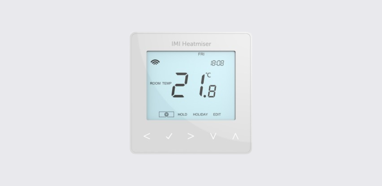
LCD Display in Thermostat Mode
| Display Item | Meaning |
| Mesh symbol | Connected to neoHub |
| Day indicator | Shows day of the week |
| Frost icon | Frost protection is active |
| Flame symbol | Heating demand is active; flashes during optimum start |
| Holiday icon | Holiday mode is active |
| Floor limit symbol | Floor probe has reached the configured floor limit |
| Floor/Room Temp | Shows active displayed sensor mode |
| Set | Current set point is being changed |
| Program indicator | Shows active comfort level during programming |
| Main menu | Shows selected menu option |
| Keypad lock | Keypad is locked |
| Temperature | Shows current sensor temperature |
| Temperature format | °C or °F |
| Hold Left | Temperature hold is active |
| Time/Day/Month/Year | Used for clock, calendar, and holiday setup |
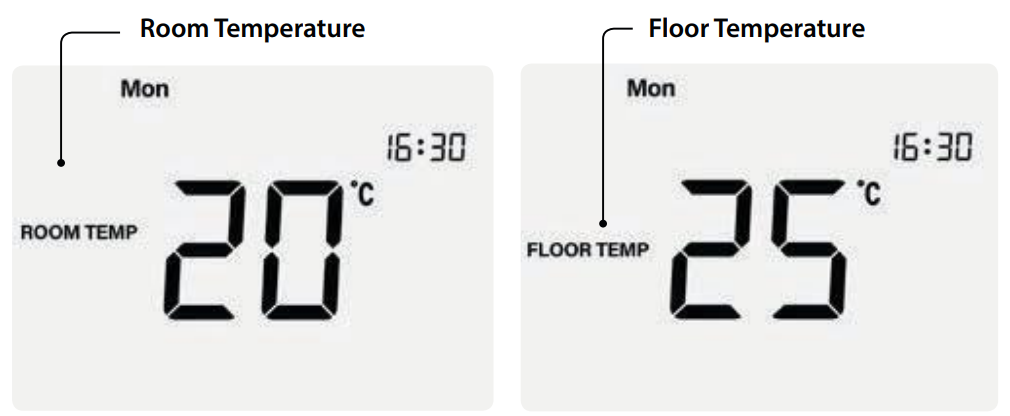
Temperature Display and Sensor Options
The neoStat can be configured to use:
- Built-in air sensor
- Remote air sensor
- Floor sensor only
- Built-in sensor and floor sensor
- Remote air sensor and floor sensor
The screen shows either Room Temp or Floor Temp depending on the sensor mode.
When both air and floor sensors are used, room temperature appears by default. To view the current floor temperature, press and hold the Left and Right arrow keys for 5 seconds.
Setting the Clock
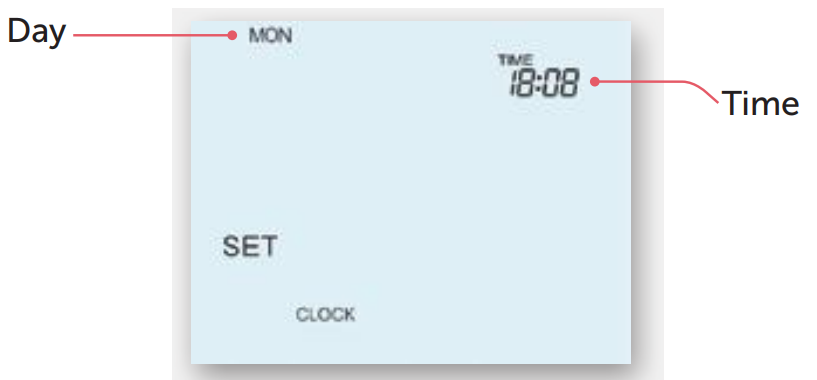
- Use Left/Right to scroll to the power icon.
- Press and hold Tick to turn off the display.
- Use the Right arrow to select CLOCK.
- Press Tick.
- Use Up/Down to set the year.
- Press Tick.
- Repeat for month, date, and time.
- Press Tick to save.
- Use the Down arrow to scroll back to the power icon.
- Press Tick to turn the display on.
Comfort Levels and Programming
The neoStat supports these program modes:
| Program Mode | Description |
| Weekday/Weekend | One schedule for weekdays and another for weekends |
| 7 Day | Each day can have its own schedule |
| 24 Hour | Same schedule every day |
| Non-programmable | Manual temperature control only |
When thermostats are connected to the mesh network, program mode is configured through the neoApp.
Default Comfort Levels
| Period | Time | Temperature |
| Wake | 07:00 | 21°C |
| Leave | 09:00 | 16°C |
| Return | 16:00 | 21°C |
| Sleep | 22:00 | 16°C |
Unused comfort levels should be set to –:–.
How to Set Comfort Levels
- Scroll to EDIT.
- Press Tick.
- Use Left/Right to select the day or period.
- Press Tick.
- When WAKE flashes, press Tick.
- Use Up/Down to set the hour.
- Press Tick.
- Use Up/Down to set the minutes.
- Press Tick.
- Use Up/Down to set the temperature.
- Press Tick.
- Move to LEAVE and repeat the same steps.
- Repeat for all comfort levels.
- Set unused periods to –:–.
- Scroll to DONE and press Tick.
Temperature Control
To change the set temperature manually:
- Press Up or Down.
- The screen shows SET and the desired temperature.
- Use Up/Down to adjust the value.
- Press Tick to confirm.
This new temperature remains active until the next programmed comfort level. Then the thermostat returns to the programmed schedule.
Temperature Hold
Temperature Hold overrides the current program for a chosen duration.
How to Set Temperature Hold
- Scroll to HOLD.
- Press Tick.
- Use Up/Down to set the hold period.
- Press Tick.
- Use Up/Down to set the hold temperature.
- Press Tick.
The display shows HOLD LEFT and the remaining time. When the hold period ends, the thermostat returns to the normal program.
Cancel Temperature Hold
With HOLD selected on the main menu, press Tick, then press Tick again while Cancel is highlighted.
Locking and Unlocking the neoStat
The neoStat includes a keypad lock with a four-digit PIN.
Lock the neoStat
- Scroll to HOLD.
- Press and hold Tick for 10 seconds.
- The display shows 0000.
- Use Up/Down to enter the first two digits.
- Press Tick.
- Use Up/Down to enter the second two digits.
- Press Tick.
- The keypad lock icon appears.
Unlock the neoStat
- Press Tick once.
- Enter the four-digit PIN using Up/Down and Tick.
- The display unlocks and returns to the main screen.
Frost Mode
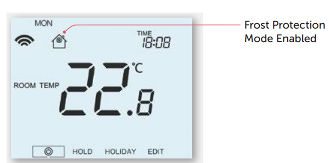
Frost mode helps protect the property from low-temperature conditions.
How Frost Mode Works
- The frost icon appears on screen.
- Heating only turns on if the room temperature drops below the frost protection temperature.
- The flame symbol appears if heating is active.
Enable or Disable Frost Mode
- Scroll to the Power icon.
- Press Tick.
- The frost icon toggles on or off each time Tick is pressed.
Power On and Off
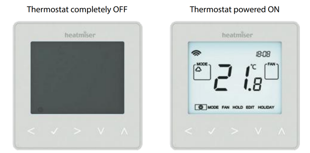
The flame icon shows active heat demand. If the flame icon is absent, heating is not required, but the thermostat remains active.
Turn Off Completely
- Scroll to the Power icon.
- Hold Tick for about 3 seconds.
- The display goes blank.
- Heating output turns off.
Turn On
Press Tick once.
Holiday Mode
In thermostat mode, Holiday mode reduces the set temperature to the frost protection temperature. In time clock mode, Holiday mode keeps the timed output OFF.
Set Holiday Mode
- Scroll to HOLIDAY.
- Press Tick.
- Use Up/Down to set the year.
- Press Tick.
- Set the month, date, and time.
- Press Tick to confirm each step.
The holiday period starts immediately and ends at the configured time and date.
Cancel Holiday Mode
- Scroll to HOLIDAY.
- Press Tick.
- When CANCEL appears, press Tick.
Optional Thermostat Features
| Feature | Description | Settings |
| 01 | Pairing to neoHub | Adds zone to neoHub |
| 02 | Switching differential | 0.5°C, 1.0°C, 2.0°C, 3.0°C |
| 03 | Frost protection temperature | 7°C to 17°C |
| 04 | Output delay | 00 to 15 minutes |
| 05 | Up/down temperature limit | 00°C to 10°C |
| 06 | Sensor selection | Built-in, remote air, floor, built-in + floor, remote air + floor |
| 07 | Floor temperature limit | 20°C to 45°C |
| 08 | Optimum start | 00 to 05 hours |
| 09 | Rate of change | Minutes to raise by 1°C |
| 10 | Not used | Not used |
| 11 | Not used | Not used |
| 12 | Program mode | Non-programmable, weekday/weekend, 7 day, 24 hour |
| 13 | Temperature format | °C or °F |
Important note: the manual states that the neoStat 12V must not be used to control electric underfloor heating.
How to Adjust Optional Settings
- Use Left/Right to scroll to the power icon.
- Press and hold Tick for 3 seconds.
- When SETUP appears, press Tick once.
- Use Up/Down to scroll through features.
- Use Left/Right to adjust the selected setting.
- Press Tick to confirm and exit.
Re-Calibrating the Thermostat
Re-Calibration Steps
- Scroll to the Power icon.
- Press and hold Tick to turn the display off.
- Press and hold Tick + Down together for 10 seconds.
- The current temperature appears.
- Use Up/Down to set the new temperature value.
- Press Tick to confirm.
- Use the Down arrow to highlight the power icon.
- Press Tick once to turn the thermostat on.
Error Codes
The thermostat screen displays error codes when faults are detected.
| Error Code | Meaning | Recommended Action |
| E0 | Internal sensor fault | Contact support or installer |
| E1 | Remote floor probe not connected, wired incorrectly, or faulty | Check floor probe wiring and probe type |
| E2 | Remote air probe not connected, wired incorrectly, or faulty | Check remote air probe wiring |
Floor Temperature Sensor Probe Type
The neoStat 12V is supplied with a 10K floor sensor probe and is also compatible with 12K and 15K probes.
How to Change Probe Type
- Scroll to the power icon.
- Press and hold Tick to turn the display off.
- Press and hold Up + Down together for 5 seconds.
- Use Left/Right to choose:
- 10 = 10K probe
- 12 = 12K probe
- 15 = 15K probe
- Press Tick to confirm.
The manual states this change should only be carried out by an experienced technician who has verified the probe value being used.
Wiring Diagram
The neoStat 12V connects to the UH8-N wiring centre. The UH8-N supports up to eight 12V thermostats or timers.
Thermostat Mode Wiring
The wiring diagram shows:
- 12VDC supply
- UH8-N connection
- Optional floor probe
- Optional remote air probe
- Terminals including RT2, RT1, -, A2, A1, +
The manual recommends CAT5-FTP or BELDEN 9538 for network devices connected to the UH8-N and instructs installers to connect the screen to S/Earth at the UH8-N.
Factory Reset
Factory reset clears all setup and pairing parameters. After reset, setup and pairing must be repeated.
Factory Reset Steps
- Scroll to the power icon.
- Press and hold Tick to turn the display off.
- SETUP appears.
- Press and hold Tick for 10 seconds.
- All icons appear for 2 seconds.
- The number 1 or 2 flashes.
- Use Left/Right to choose:
- Mode 1 = Thermostat
- Mode 2 = Time Clock
- Press Tick to confirm.
Mode 2: Time Clock Mode
In Time Clock Mode, the neoStat 12V controls timed output instead of temperature-based heating.
LCD Display in Time Clock Mode
| Display Item | Meaning |
| Mesh symbol | Connected to neoHub |
| Day indicator | Shows day of the week |
| Holiday icon | Time clock is in holiday mode |
| Set | Settings are being changed |
| Program indicator | Shows switching period being edited |
| Main menu | Shows selected option |
| Keypad lock | Keypad is locked |
| Timer status | Shows current timed output state |
| Hold Left | Timer hold is active |
| Time/Day/Month/Year | Used for clock, calendar, and holiday setup |
Setting Switching Times in Time Clock Mode
- Scroll to EDIT.
- Press Tick.
- Use Left/Right to select the day or period.
- Press Tick.
- Switching time 1 flashes and the current ON time appears.
- Press Down to view the OFF time.
- Select a switching time and press Tick.
- Set ON hours with Up/Down, then press Tick.
- Set ON minutes, then press Tick.
- Set OFF hours, then press Tick.
- Set OFF minutes, then press Tick.
- Press the Right arrow to move to switching time 2.
- Repeat for all periods.
- Set unused periods to –:–.
- Scroll to DONE and press Tick.
Timer Override
Timer Override turns the timed output on for a selected duration.
How to Use Timer Override
- Use Up/Down to set the override duration, such as 02:00 hours.
- Press Tick to confirm.
- The display returns to the main screen.
- Hold Left and remaining time appear on the display.
Time Clock Optional Features
| Feature | Description | Settings |
| 01 | Pairing to neoHub | Used to connect the time clock to neoHub |
| 02 | Program mode | Weekday/weekend, 7 day, or 24 hour |
Time Clock Programming Modes
| Mode | Description |
| Weekday/Weekend | 4 ON/OFF switching times for weekdays and 4 for weekends |
| 7 Day | Each day has 4 ON/OFF switching times |
| 24 Hour | All days use the same ON/OFF switching times |
Time Clock Mode Wiring
Time clock mode also connects to the UH8-N wiring centre. The same network wiring guidance applies:
- UH8-N supports up to eight 12V thermostats/timers.
- Use CAT5-FTP or BELDEN 9538.
- Connect the cable screen to S/Earth at the UH8-N.
- Installation must be completed by a qualified electrician.
Troubleshooting Guide
| Problem | Possible Cause | Recommended Action |
| Mesh symbol disappears | neoHub connection lost | Check neoHub power, router connection, and app pairing |
| Heating does not turn on | Room temperature may already be above set point | Check flame icon and set temperature |
| Floor temperature limit appears | Floor probe has reached configured limit | Check Feature 07 floor limit |
| Buttons do not respond | Keypad lock is active | Unlock with the four-digit PIN |
| E0 appears | Internal sensor fault | Contact support |
| E1 appears | Floor probe issue | Check probe wiring and probe type |
| E2 appears | Remote air probe issue | Check remote air probe wiring |
| Time clock output stays off | Holiday mode or schedule issue | Check holiday mode and switching times |
| Temperature reading seems inaccurate | Calibration may need adjustment | Use recalibration steps carefully |
| Probe value is wrong | Incorrect floor probe type selected | Confirm probe value and set 10K, 12K, or 15K |
Support and Contact
IMI Heatmiser provides support, technical specifications, PDFs, FAQs, and online resources.
IMI Heatmiser Support
Support phone: +44 (0)1254 669090
Website: www.heatmiser.com
Address:
IMI Heatmiser
Units 1-5 Hurstwood Court, Mercer Way
Shadsworth Business Park, Blackburn
Lancashire, BB1 2QU
United Kingdom
The manual states that Heatmiser UK Ltd declares the radio equipment complies with Directive 2014/53/EU. RF frequency is listed as 2.4GHz 3.54dBm.