| Document Detail | Information |
| Document Type | Installation and User Guide |
| Brand Name | Heatmiser |
| Product Name | 4-Channel Time Clock |
| Model Number(s) | TM4 V2; manual text also refers to the model as TM4 |
| Series | Time Clock Series |
| File Size | 499.2 KB |
| Number of Pages | 16 |
| Languages Covered | English |
Heatmiser 4-Channel Time Clock TM4 V2
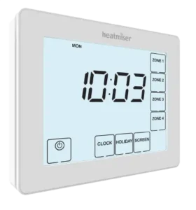
The Heatmiser TM4 V2 is a four-channel programmable time clock designed to independently control up to four timed outputs. Each zone can have its own switching schedule and can be configured for either 5/2-day Weekday/Weekend programming or 7-day programming.
The TM4 also provides per-zone Auto, Off, and Constant operating modes, temporary Boost control, Holiday shutdown for all four outputs, and a Copy function for transferring switching times from one zone to other zones. In normal operation, the display shows the current time and can be changed temporarily to show the operating status of an individual zone.
Main Functions
The TM4 V2 provides four individually selectable zones labeled Zone 1, Zone 2, Zone 3, and Zone 4. The front-panel controls shown in the manual provide access to the clock, holiday settings, zone schedules, operating modes, boost periods, and display functions.
Important operating functions include:
- Four independently controlled timed outputs.
- Four ON/OFF switching periods for each zone.
- 5/2-day Weekday/Weekend programming.
- 7-day programming.
- Auto, Off, and Constant modes for each zone.
- Temporary Boost operation.
- Holiday mode that disables all four timed outputs.
- Copy function for duplicating one zone’s switching times to other zones.
- Individual zone-status display.
- 24-hour digital clock.
- Four switched-live output channels.
Installation Requirements
The Heatmiser TM4 V2 is designed for flush mounting.
The manual specifies a wall back box with a minimum depth of 35 mm. The time clock should be positioned approximately at eye level. It should not be installed beside a direct heat source because nearby heat may affect operation, and the LCD should not be pressed forcefully because this may cause permanent damage.
Installing the Heatmiser TM4 V2
The four-stage installation process is illustrated on pages 3-4 of the manual.
Step 1: Separate the Front From the Back Plate
Using a small screwdriver, slightly loosen the retaining screw on the bottom edge of the time clock.
Carefully separate the front portion from the rear mounting plate.
Step 2: Connect the Wiring
Place the front section somewhere safe while installation is completed.
Terminate the electrical connections according to the wiring diagram supplied on page 14 of the manual.
Step 3: Mount the Back Plate
Secure the back plate firmly into the recessed wall back box.
Step 4: Refit the Front Panel
Position the front panel over the mounted back plate.
Locate the connection pins into their socket, insert the top edge first, then push the lower edge into position. Tighten the retaining screw to secure the front panel.
LCD Display and Control Guide
The LCD diagram on pages 5-6 identifies the TM4’s main status indicators and operating controls.
| No. | Display or Control | Function |
| 1 | Day Indicator | Displays the current day |
| 2 | Copy | Used to copy switching times from one zone to another |
| 3 | ON UNTIL / OFF UNTIL | Shows the current operational status of the timed output |
| 4 | Timer Status | Displays the current status of the selected timed output |
| 5 | Left Up/Down Keys | Increase or decrease values in the left digit group |
| 6 | Right Up/Down Keys | Increase or decrease values in the right digit group |
| 7 | Select Zone | Indicates that a zone selection is required |
| 8 | Boost Left / Holiday Left | Shows the remaining Boost time or Holiday duration |
| 9 | Power / Cancel | Power turns off the display; Cancel exits setup or programming |
| 10 | Setup / Programming Keys | Used to move through setup and programming functions |
| 11 | Off / Constant / Auto | Shows the selected operating mode for the zone |
| 12 | Zone / Time Selection Keys | Used when selecting zones and switching periods |
Front-Panel Programming Keys
The main touchscreen controls shown on the TM4 display include:
| Control | Main Purpose |
| Power / Cancel | Turns off the display or leaves a setup/programming screen |
| Edit | Opens a selected zone’s switching schedule |
| Clock / Day | Sets the current clock and chooses days during programming |
| Holiday / Boost | Configures Holiday mode or a temporary Boost |
| Screen / Mode | Changes screen or zone operating mode |
| Done | Saves the current setup and exits |
| Zone 1-4 | Selects one of the four controlled outputs |
| Time 1-4 | Selects one of four switching periods |
| Copy | Copies a programmed zone schedule to other zones |
Normal Run Mode
During normal operation, the main screen shows the current time.
To check a particular output:
- Press Zone 1, Zone 2, Zone 3, or Zone 4.
- The screen changes to display information for that selected zone.
- Press DONE when finished to return to the main clock screen.
The example in the manual shows an individual zone displaying an ON UNTIL time and its current Auto status.
Setting the Clock
The current time and day should be set before zone schedules are programmed.
Clock Setup
- Press CLOCK.
- Use the left Up/Down controls to adjust the hour.
- Use the right Up/Down controls to adjust the minutes.
- Press DAY to change the current day.
- Press DONE to confirm the settings and exit.
The clock-setting screen separates the hours and minutes into independent digit groups for faster adjustment.
Selecting 5/2-Day or 7-Day Programming
Each of the four zones can be independently configured to use either a Weekday/Weekend schedule or separate daily schedules.
| Setting | Programming Mode |
| 00 | 5/2 Day — Weekday/Weekend |
| 01 | 7 Day |
How to Change a Zone’s Programming Mode
- Select the zone, such as ZONE 1.
- Press DAY.
- Use the Up/Down controls to choose:
- 00 for 5/2 Day mode.
- 01 for 7 Day mode.
- Press DONE to save and exit.
This process can be repeated for the other zones as needed.
5/2-Day Programming
In 5/2 Day mode, Monday through Friday share one group of switching times, while Saturday and Sunday use a separate weekend schedule.
When weekday programming is selected, the display shows:
Mon Tue Wed Thu Fri
The weekend schedule can then be set separately.
7-Day Programming
In 7 Day mode, each day can have its own set of switching times.
During programming, an individual day such as Mon appears on the display. The Day control can then be used to move through the remaining days.
Switching Times
Each TM4 zone provides four ON/OFF switching periods:
- Time 1
- Time 2
- Time 3
- Time 4
This allows one zone to switch on and off up to four times during its programmed day or day group.
How to Program Switching Times
- Select the required zone, such as ZONE 1.
- Press EDIT.
- The display shows the current programming day or day group.
- Press DAY to select the day or group to edit.
- Use the Up/Down controls to set the ON time.
- Press OFF to move to the OFF-time setting.
- Use the Up/Down controls to set the OFF time.
- Repeat the procedure for Time 2, Time 3, and Time 4.
- Press DONE to save and exit.
In 5/2 mode, Monday-Friday appear together during weekday programming. In 7-day mode, individual days are displayed separately.
Understanding ON UNTIL and OFF UNTIL
The TM4 status screen uses ON UNTIL and OFF UNTIL to show what the selected output is currently doing in relation to its next programmed switching point.
For example:
- ON UNTIL indicates that the zone is currently active and shows when its programmed ON state ends.
- OFF UNTIL indicates that the zone is currently inactive and shows when its next programmed ON state begins.
These indicators provide a quick way to check the current timed-output status without opening the full schedule.
Copying Switching Times Between Zones
The TM4 has a Copy function so that the same schedule does not have to be entered manually for every zone.
How to Copy a Zone Schedule
- Select the zone containing the schedule to be copied.
- Press EDIT.
- Press COPY.
- Select each destination zone that should receive the same switching times.
- Press DONE to confirm and exit.
The copied switching times are then applied to the selected destination zones.
Zone Operating Modes
Each zone has three operating modes:
| Mode | Operation |
| Auto | The zone follows its programmed switching times |
| Off | The zone remains switched off |
| Constant | The zone remains switched on continuously |
Changing the Zone Mode
- Select the required zone.
- Press MODE repeatedly until the desired mode appears.
- Press DONE to save and exit.
The selected Off, Constant, or Auto status is shown on the LCD for the zone.
Boost Facility
Each zone includes a Boost function that temporarily turns the selected zone on for a chosen number of hours.
This is useful when extra operating time is required but the normal programmed schedule should remain unchanged.
How to Start a Boost
- Select the required zone.
- Press BOOST.
- Use the Up/Down controls to enter the required Boost duration in hours.
- Press DONE.
The remaining Boost period appears on the screen.
Canceling a Boost
Repeat the Boost procedure and reduce the duration to:
00 hours
The temporary Boost ends without altering the normal programmed switching times.
Holiday Mode
Holiday mode disables all four timed outputs for the specified number of days.
When the Holiday period ends, the TM4 automatically returns to its programmed switching schedules.
Setting a Holiday
- Press HOLIDAY.
- Use the controls to enter the required number of Holiday days.
- Press DONE to confirm.
The remaining Holiday duration is shown on the screen.
When the Holiday Starts
A Holiday period begins at 00:00 on the following day, not immediately.
The manual gives the example that if a two-day Holiday is entered on Friday, Saturday is the first Holiday day and the normal schedule resumes at 00:00 on Monday.
Canceling Holiday Mode
Enter the Holiday setup again and reduce the Holiday period to:
00 days.
Power and Cancel Function
The Power/Cancel control serves two purposes depending on the current screen.
Power
Pressing Power once turns off the TM4 display.
Cancel
During a setup or programming operation, the same control is used to leave the current operation without continuing through the programming sequence.
The LCD reference section identifies this combined control as Power/Cancel.
TM4 V2 Wiring
The wiring diagram on page 14 shows a 230VAC supply connected to the TM4, together with four independently switched live outputs.
Wiring Terminals
| Terminal | Function Shown in Manual |
| N | Neutral |
| L | Live |
| CH1 | Switched Live Channel 1 |
| CH2 | Switched Live Channel 2 |
| CH3 | Switched Live Channel 3 |
| CH4 | Switched Live Channel 4 |
The diagram shows the incoming 230VAC Live and Neutral supplying the time clock, with separate switched-live connections leaving CH1 through CH4.
Four-Channel Output Arrangement
The four channels correspond to the four front-panel zones:
| User Interface | Electrical Output |
| Zone 1 | CH1 |
| Zone 2 | CH2 |
| Zone 3 | CH3 |
| Zone 4 | CH4 |
This arrangement allows four timed circuits to be scheduled and controlled separately from the same TM4 unit.
Installation Safety
Electrical installation should follow the manufacturer’s page 14 wiring diagram and applicable local electrical requirements.
The unit uses a 230VAC supply, so electrical wiring should be completed by a suitably qualified installer rather than through user experimentation. The front panel should only be refitted after the back plate and electrical terminations have been completed correctly.
Quick Operating Reference
| Task | Controls |
| Check a zone | Press Zone 1-4 |
| Return to main display | DONE |
| Set clock | CLOCK → hour/minute controls → DAY → DONE |
| Choose 5/2 or 7 Day | Zone → DAY → 00/01 → DONE |
| Program switching time | Zone → EDIT → DAY → ON/OFF times → DONE |
| Copy schedule | Source Zone → EDIT → COPY → Destination Zones → DONE |
| Change zone mode | Zone → MODE → Auto/Off/Constant → DONE |
| Start Boost | Zone → BOOST → duration → DONE |
| Cancel Boost | Set Boost duration to 00 |
| Set Holiday | HOLIDAY → number of days → DONE |
| Cancel Holiday | Set Holiday duration to 00 days |
Customer Support Information
Heatmiser provides direct support and technical-information contacts in the manual.
| Support Detail | Information |
| Company | Heatmiser UK Ltd |
| Support Phone | +44 (0)1254 669090 |
| Website | www.heatmiser.com |
| @heatmiseruk | |
| facebook.com/thermostats | |
| Address | Units 1-5 Hurstwood Court, Mercer Way, Shadsworth Business Park, Blackburn, Lancashire, BB1 2QU, United Kingdom |
| Document Revision | Rev. 1.1 |
Frequently Asked Questions
How many zones can the Heatmiser TM4 V2 control?
The TM4 provides four separately selectable zones, with corresponding Zone 1-4 controls and CH1-CH4 switched-live outputs.
Can each TM4 zone have a different schedule?
Yes. Each zone can be programmed independently and can use either 5/2-day or 7-day programming.
How many switching periods are available for each zone?
Each zone provides four ON/OFF time periods, labeled Time 1 through Time 4.
What is the difference between Auto, Off, and Constant mode?
Auto follows the programmed switching schedule. Off keeps the selected zone off. Constant keeps it switched on continuously.
How can a zone be turned on temporarily without changing its schedule?
Use the Boost function. Select the zone, press Boost, enter the number of hours, and confirm with DONE. The normal programmed schedule remains unchanged.
What happens during Holiday Mode?
All four timed outputs are disabled for the selected Holiday duration. When the Holiday period expires, the normal programmed schedules resume automatically.
Can one zone’s schedule be copied to another zone?
Yes. Select the source zone, press EDIT and COPY, choose the destination zones, and press DONE.
What power supply does the Heatmiser TM4 V2 use?
The manual’s wiring diagram shows the TM4 connected to a 230VAC supply with Neutral, Live, and four switched-live channel outputs.