| Field | Details |
| Document Title | X2S Smart Thermostat RTH2SMC Installation and User Guide |
| Document Type | Installation and User Guide |
| Brand Name | Honeywell Home |
| Product Name | X2S Smart Thermostat |
| Model Number(s) | RTH2SMC |
| PDF File Size | 2.20 MB |
| Total Number of Pages | 72 |
| Languages Covered | English, French, Spanish |
Honeywell Home X2S Smart Thermostat RTH2SMC
The Honeywell Home X2S Smart Thermostat RTH2SMC is a WiFi-enabled programmable thermostat designed to control compatible home heating, cooling, and heat pump systems. It provides temperature control directly from the thermostat or remotely through the First Alert app.
The X2S Smart Thermostat supports multiple scheduling options, including location-based scheduling, smart scheduling, and traditional time-based programming. Location-based scheduling uses smartphone geofencing to adjust heating and cooling settings when household members leave or return home. Smart scheduling combines geofencing with programmed temperature schedules.
The thermostat also features Smart Response technology, which learns how long the heating and cooling equipment takes to reach a selected temperature. This allows the system to begin heating or cooling before a scheduled period so the desired temperature can be reached at the programmed time.Additional functions include automatic heating and cooling changeover, fan control, temporary and permanent temperature holds, maintenance reminders, WiFi alerts, and indoor temperature monitoring.
The RTH2SMC requires a 24 VAC power supply with a C-wire and is compatible with most conventional heating, cooling, and heat pump systems. It connects to the home network through 2.4 GHz or 5 GHz WiFi and uses the supplied UWP mounting system for installation.
Product Overview and Technical Specifications
The X2S RTH2SMC combines conventional thermostat controls with WiFi connectivity and smartphone-based heating and cooling management.
| Specification | Details |
| Brand | Honeywell Home |
| Manufacturer | Resideo Technologies, Inc. |
| Model Number | RTH2SMC |
| Product Name | X2S Smart Thermostat |
| Product Type | WiFi Smart Programmable Thermostat |
| Power Requirement | 24 VAC |
| C-Wire Requirement | Required |
| WiFi Compatibility | 2.4 GHz and 5 GHz |
| Mobile Application | First Alert app |
| Compatible Mobile Platforms | Android and iOS |
| Installation Location | Indoor use only |
| Mounting System | UWP mounting system |
| Compatible HVAC Systems | Most heating, cooling, and heat pump systems |
| Line-Voltage Compatibility | Not compatible with 120–240V electric baseboard heating |
| External Sensor Terminals | S terminals not supported |
| Universal Relay Terminals | U terminals not supported |
| Scheduling Options | Location-Based, Smart, and Time-Based |
| Time-Based Schedules | 1-Week, 5-2 Day, 5-1-1 Day, 7-Day |
| Daily Schedule Periods | Four |
| Temperature Units | Fahrenheit or Celsius |
| System Modes | Auto, Heat, Cool, Emergency Heat, Off |
| Fan Modes | Auto, On, Circulate |
| Automatic Changeover | Supported |
| Smart Response | Supported |
| Temporary Temperature Hold | Supported |
| Permanent Temperature Hold | Supported |
| Filter Replacement Reminders | Supported |
| WiFi and System Alerts | Supported |
| Warranty | 2-Year Limited Warranty |
The available operating modes and installer settings depend on the heating and cooling equipment connected to the thermostat.
What’s Included in the Box
The X2S Smart Thermostat package includes the thermostat and the installation components required for the supported mounting arrangement.
| Included Component | Purpose |
| X2S Smart Thermostat | Controls compatible heating and cooling equipment |
| UWP Mounting System | Provides the wall-mounting and wire terminal connections |
| Screws | Secure the mounting system to the wall |
| Wall Anchors | Support wall installation |
| Literature | Provides installation and operating instructions |
| Wire Labels | Identify existing thermostat wires during replacement |
| Replacement Accent Piece | Changes the thermostat’s exterior appearance |
Thermostat Accent Pieces
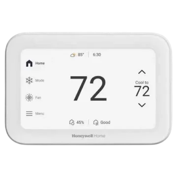
The thermostat is supplied with white and gray accent pieces to accommodate different appearance preferences.
The accent piece can be removed and replaced without changing the thermostat’s operating settings.
Tools Required for Installation
The following tools and items are used during the installation process.
Required Tools
- Phillips screwdriver.
- Small flat-head screwdriver.
- Pencil.
- Level.
- Smartphone for photographing existing wiring.
- Home WiFi password.
- First Alert app for app-based setup.
Additional Tools That May Be Needed
- Wire stripper.
- Needle-nose pliers.
- Drill.
- 3/16-inch drill bit.
System Compatibility
The Honeywell Home X2S RTH2SMC is designed for compatible low-voltage heating and cooling equipment.
Compatible Heating and Cooling Systems
The thermostat supports most conventional heating, cooling, and heat pump systems.
The installer setup menu includes configuration options for conventional forced-air heating, heat pumps, radiant boiler heating, and cooling-only applications.
Power Supply Requirement
The thermostat requires a 24 VAC power supply and a C-wire.
The C-wire provides the common connection needed for thermostat power.
WiFi Requirements
The thermostat supports a home WiFi network operating on either:
- 2.4 GHz.
- 5 GHz.
An Android or iOS smartphone or tablet is used for First Alert app setup.
Unsupported Systems and Connections
| System or Connection | Compatibility |
| Most 24 VAC conventional HVAC systems | Supported |
| Compatible heat pump systems | Supported |
| 120–240V electric baseboard heating | Not supported |
| S terminals for indoor/outdoor sensors | Not supported |
| U terminals for relays | Not supported |
If an existing thermostat has wires connected to terminals outside the supported wiring list, additional wiring assistance is required before installation.
Safety Instructions and Important Warnings
The following precautions must be followed before removing an existing thermostat or connecting the X2S RTH2SMC.
Electrical Hazard
Warning: Electrical shock or equipment damage can occur if power is not disconnected before installation.
Turn off power to the heating and cooling system at the circuit breaker or equipment power switch before removing the existing thermostat.
Check for Line-Voltage Wiring
The X2S Smart Thermostat must not be connected to a 120V or 240V line-voltage thermostat circuit.
An existing thermostat may use line voltage if it has thick black wires connected with wire nuts or is marked for 120V or higher operation.
If either condition applies, the X2S is not compatible with that installation.
Protect the Heating and Cooling Equipment
Compressor protection is bypassed during equipment testing.
Avoid rapidly cycling the compressor during testing because this can damage the equipment.
Mercury Disposal Warning
If the old thermostat contains mercury in a sealed tube, it must not be discarded with ordinary household trash.
The local waste management authority should be contacted for proper recycling and disposal instructions.
Electronic Waste Disposal
The X2S thermostat must not be discarded with normal household waste at the end of its service life.
Use an authorized electronic waste collection facility or approved recycling center.
Parts, Controls, and Display Guide
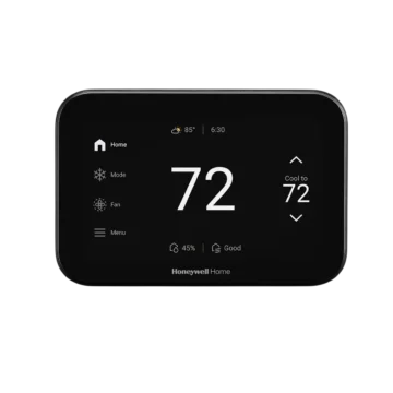
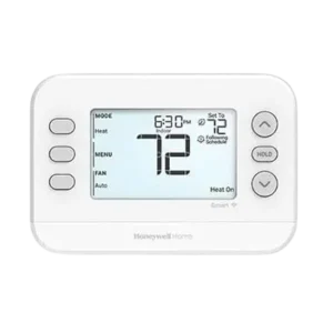
The X2S RTH2SMC has a central digital display with three buttons on the left side and three controls on the right.
The function of the left-side buttons changes according to the labels displayed on the screen.
Main Controls
| Control | Function |
| MODE | Changes the heating and cooling system mode |
| MENU | Opens settings, schedules, alerts, and configuration options |
| FAN | Changes the fan operating mode |
| Up Arrow (↑) | Increases the selected temperature or setting |
| HOLD | Cycles through temperature hold selections |
| Down Arrow (↓) | Decreases the selected temperature or setting |
Context-Sensitive Menu Buttons
During setup and programming, the left-side controls may display labels such as:
| Screen Label | Function |
| SELECT | Opens or confirms a menu selection |
| NEXT | Moves to the next setting |
| SAVE | Saves the selected value |
| SAVE & EXIT | Saves settings and returns to the home screen |
| EXIT | Leaves a menu |
| DISMISS | Resets an active reminder |
| USING APP | Starts setup through the First Alert app |
| ON DEVICE | Starts configuration on the thermostat |
Thermostat Display Indicators
| Display Indicator | Meaning |
| Indoor | Current indoor temperature |
| Set To | Selected target temperature |
| Heat | Heating mode |
| Cool | Cooling mode |
| Auto | Automatic system or fan operation, according to its location |
| Heat On | Heating equipment is being requested |
| Cool On | Cooling equipment is being requested |
| Aux Heat On | Auxiliary heating demand |
| Hold | Temperature hold control |
| Following Schedule | Thermostat is operating according to a programmed schedule |
| Active Recovery | Smart Response is preparing for an upcoming scheduled temperature |
| Waiting for Equipment | Compressor protection delay is active |
| Alert Icon | An active alert is present |
| Reminder Icon | A maintenance or other reminder is present |
| WiFi Icon | Wireless network connection status |
Removing the Existing Thermostat
The existing thermostat must be removed carefully so that all wires can be correctly identified before the new UWP mounting system is installed.
Step 1: Turn Off Power
- Locate the circuit breaker or switch controlling the heating and cooling system.
- Switch off the power.
- Leave the system disconnected while working with the wiring.
Step 2: Confirm That the System Is Off
- Set the existing thermostat to Heat or Cool.
- In Heat Mode, set the target temperature above the current room temperature.
- In Cool Mode, set the target below the current room temperature.
- Wait up to five minutes.
If the heating or cooling equipment does not start, the system has been switched off.
If the old digital thermostat display is already blank, this test can be skipped.
Step 3: Remove the Existing Faceplate
Carefully remove the front cover of the existing thermostat.
Some faceplates pull away directly, while others have screws, clasps, or release buttons.
Do not disconnect the thermostat wires at this stage.
Step 4: Check the Wiring Voltage
Inspect the wiring to determine whether the existing thermostat uses line voltage.
If the wiring contains thick black wires with wire nuts, or the existing thermostat uses 120V or higher, the X2S must not be installed on that circuit.
Step 5: Photograph the Wiring
Take a clear photograph of the existing wire connections.
The photograph should show the terminal letters and the wires connected to each terminal.
If wire colors are faded or repeated, apply the supplied wire labels to identify them.
Step 6: Identify Existing Jumpers
A jumper is a short wire or metal connection joining two thermostat terminals.
It may resemble a small staple or colored wire.
Record any existing jumpers but do not include them in the count of thermostat wires.
The X2S UWP mounting system does not require the old jumpers.
Step 7: Record the R-Wire Connections
Determine which of the following terminals have connected wires.
| Existing Terminal | Wire Identification |
| R | Record wire color |
| Rh | Record wire color |
| Rc | Record wire color |
These connections determine the correct R-slider position on the UWP mounting system.
Step 8: Record the Remaining Wires
The manufacturer’s wiring checklist includes the following terminal labels.
| Terminal | Record Existing Wire |
| Y | Wire color |
| Y2 | Wire color |
| G | Wire color |
| C | Required C-wire |
| A or L/A | Wire color |
| O/B | Wire color |
| W2 or AUX | Wire color |
| E | Wire color |
| W | Wire color |
| K | Wire color |
The S and U terminals are not supported.
If wires are connected to terminals outside the documented list, wiring compatibility must be checked before proceeding.
Step 9: Disconnect the Existing Thermostat
- Use a screwdriver to release each wire.
- Apply the appropriate wire label as the wire is disconnected.
- Match the label to the original terminal letter.
- Remove the old wall plate.
To prevent the thermostat wires from falling back into the wall, they can be wrapped around a pencil.
Installing the UWP Mounting System
The Honeywell Home X2S uses the UWP mounting system for wire connections and wall installation.
Step 1: Insert the Wires Through the UWP
- Open the UWP mounting system.
- Feed the existing thermostat wires through the rear opening.
- Arrange the wires so they can reach their assigned terminals.
The manufacturer specifies that at least 1/4 inch of each wire must be exposed for terminal insertion.
The installation illustration identifies a wire preparation range of approximately 1/4 to 3/8 inch.
Step 2: Mark the Mounting Positions
- Position the UWP against the wall.
- Use a level to align the mounting system.
- Mark the required anchor locations with a pencil.
Step 3: Install the Wall Anchors
- Drill the marked holes using a 3/16-inch drill bit.
- Insert the supplied wall anchors.
- Position the anchors so they are flush with the wall.
The supplied anchors are recommended for mounting the thermostat.
Setting the R/Rc Slider Switch
The R-slider switch must be configured according to the number of R power wires in the existing installation.
Installation With One R Wire
If there is one R, Rh, or Rc wire:
- Move the R-slider switch to the UP position.
- Insert the single R, Rh, or Rc wire into the R terminal.
Installation With Two R Wires
If there are separate R/Rh and Rc wires:
- Move the R-slider switch to the DOWN position.
- Insert the Rc wire into the Rc terminal.
- Insert the R or Rh wire into the R terminal.
R-Slider Position Reference
| Existing Wiring | Slider Position | Connections |
| One R, Rh, or Rc wire | UP | Single wire to R |
| Two wires: R/Rh and Rc | DOWN | Rc to Rc; R/Rh to R |
The manufacturer’s conventional wiring notes also address existing systems with R and RH wires: with the slider down, the existing R wire is connected to Rc and the RH wire to R.
Wiring the X2S Smart Thermostat
The UWP mounting system provides terminals for connecting the thermostat to compatible heating and cooling equipment.
Wiring must be based on the existing terminal identification and the appropriate conventional or heat pump wiring instructions.
Connecting the Wires to the UWP
- Refer to the photograph and wire labels recorded during removal.
- Identify the corresponding UWP terminal.
- Press the terminal tab to open the connection.
- Insert the wire into the inner terminal hole.
- Release the tab so the wire remains secured.
- Repeat for the remaining wires.
Only one wire is inserted into each terminal.
Conventional Heating and Cooling Systems
For conventional systems, the R/Rc slider arrangement must match the original wiring.
If separate R and Rc supply wires are required, the slider must be in the down position.
The existing wire labels and the manufacturer’s wiring diagram determine the remaining terminal connections.
Heat Pump Wiring
Heat pump systems use a different wiring arrangement from conventional heating and cooling systems.
The manufacturer’s heat pump wiring instructions specify:
- Keep the R-slider in the UP position for the illustrated one-wire heat pump arrangement.
- If the old thermostat has both V and VR wires, stop installation and contact a qualified contractor.
- If the old thermostat has separate O and B wires, connect B to C as directed by the manufacturer’s diagram. If another wire already occupies C, stop and contact a qualified contractor.
Important: The W terminal must not be used for heat pump applications. Auxiliary heating must be connected to AUX or E according to the appropriate wiring arrangement.
Unsupported Wiring Conditions
The X2S does not support S terminals for indoor or outdoor sensors or U relay terminals.
Unlisted wiring connections require additional compatibility assistance.
Checking the Completed Wiring
Before mounting the thermostat:
- Compare the new terminal connections with the photograph of the old thermostat.
- Confirm that each wire is connected to the intended terminal.
- Check the R-slider position.
- Confirm that the connections are secure.
Mounting the Thermostat and Restoring Power
After the wiring has been completed, the UWP and thermostat can be secured.
Step 1: Mount the UWP
- Position the wired UWP against the wall.
- Secure it using the supplied screws.
- Use all three #6, 1-1/2-inch screws specified in the installation instructions.
- Close the UWP access door.
Step 2: Attach the Thermostat
- Align the X2S thermostat with the UWP.
- Push the thermostat onto the mounting system.
- Snap it firmly into place.
Step 3: Restore Power
Turn on the circuit breaker or heating and cooling system power switch.
Step 4: Check the Initial Setup Screen
Return to the thermostat.
The screen should display SETUP.
Two setup methods are available:
- USING APP.
- ON DEVICE.
The required method can now be selected.
Setting Up the X2S With the First Alert App
The First Alert app provides guided configuration and connection to the thermostat.
Step 1: Select Using App
On the thermostat’s SETUP screen, select USING APP.
Step 2: Download the First Alert App
Install the First Alert app on a compatible Android or iOS device.
The app is available through the Apple App Store and Google Play Store.
Step 3: Open the Application
Launch the First Alert app.
The thermostat may appear in the app under Thermostat Found.
Step 4: Select the Thermostat
If the X2S appears under Thermostat Found, select SET UP NOW.
If it does not appear:
- Create a First Alert account if necessary.
- Sign in to the existing account.
- Select the X2S thermostat to install.
Step 5: Complete App-Guided Setup
Follow the remaining configuration instructions displayed in the First Alert app.
The application guides the user through the remaining thermostat setup process.
Setting Up the Thermostat Without the App
The thermostat can also be configured directly through its display.
Step 1: Select On Device
At the initial SETUP screen, select ON DEVICE.
The thermostat begins its local configuration process.
The year flashes during the initial time and date setup.
Step 2: Configure the Clock
The thermostat provides settings for a 12-hour or 24-hour clock.
Step 3: Configure the Date
The date configuration includes the year, month, and day.
Step 4: Complete Installer Setup
After the initial time and date settings, the thermostat enters the Installer Setup menu.
The heating and cooling equipment configuration must match the connected system.
Setting the Time and Date
The time and date settings can also be accessed through the thermostat menu.
How to Set the Time
- Press MENU.
- Use Up or Down to find TIME.
- Press SELECT.
- Choose the 12-hour or 24-hour clock format.
- Press NEXT.
- Use Up or Down to adjust the hour.
- Press NEXT to continue.
How to Set the Date
- Press MENU.
- Use Up or Down to find DATE.
- Press SELECT.
- Select the year and press NEXT.
- Select the month and press NEXT.
- Select the date.
- Press SAVE.
- Press EXIT.
Installer Setup (ISU)
The X2S RTH2SMC provides an Installer Setup menu for configuring the connected HVAC equipment and thermostat functions.
Not every ISU option is available for every system configuration.
How to Access Installer Setup
- Press and hold the bottom-left button and the Up Arrow simultaneously.
- Continue holding for five seconds.
- INSTALLER SETUP opens.
- The ISU number appears on the left side of the display.
- The current setting appears on the right.
- Use Up or Down to change the displayed setting.
- Press NEXT to advance to another ISU option.
- Select SAVE & EXIT when configuration is complete.
Installer Setup Options
| ISU Number | Setting | Available Options |
| 1040 | Scheduling Options | 1 = 1 Week; 2 = 5-2 Day; 3 = 5-1-1 Day; 4 = 7 Day |
| 1050 | Temperature Scale | F = Fahrenheit; C = Celsius |
| 2000 | Heating System Type | 1 = Conventional Forced Air; 2 = Heat Pump; 3 = Radiant Boiler Heat; 5 = None (Cool Only) |
| 2010 | Heating Equipment Type | Conventional forced-air or radiant heating equipment selection |
| 2060 | Reversing Valve O/B | 0 = O (energized in Cool); 1 = B (energized in Heat) |
| 2070 | Cooling/Compressor Stages | 0, 1, or 2; 1 when ISU 2000 = 2 |
| 2071 | Heating/Backup Stages | Heating stages: 1 or 2; Backup stages: 0 or 1 |
| 2180 | Backup Heat Source | 31 = Electric Forced Air |
| 3000 | System Changeover | 0 = Manual; 1 = Automatic |
| 4090 | Smart Response | 0 = No; 1 = Yes |
| 4103 | Minimum Heat Setpoint | Configurable from 32°F to 90°F |
| 7110 | Air Filter Replacement Reminder | Off or selected runtime/calendar interval |
| 14005 | Idle Screen Selection | 0 = Minimum Information; 1 = Setpoint; 2 = Maximum Information |
| 14006 | Idle Screen Message Center | 1 = Time; 4 = Indoor Humidity |
| 14007 | Home Screen Message Center | 1 = Time; 4 = Indoor Humidity |
| 14010 | Clock Format | 12-hour or 24-hour |
| 14015 | Daylight Saving Time | 0 = Off; 1 = On |
ISU 1040: Scheduling Options
The thermostat supports four time-based scheduling arrangements.
| Setting | Schedule |
| 1 | One weekly schedule repeated every day |
| 2 | Separate weekday and weekend schedules |
| 3 | Separate Monday–Friday, Saturday, and Sunday schedules |
| 4 | Individual schedule for each day of the week |
Each day supports four adjustable schedule periods.
ISU 1050: Temperature Indication Scale
This setting controls whether temperature is displayed in Fahrenheit or Celsius.
The factory default varies by model.
ISU 2000: Heating System Type
This setting identifies the connected heating equipment.
The available choices include conventional forced-air heat, a heat pump, radiant boiler heating, and cooling-only operation.
ISU 2010: Heating Equipment Type
For conventional forced-air heating, the available settings are:
| Value | Equipment Type |
| 1 | Standard Efficiency Gas Forced Air |
| 2 | High Efficiency Gas Forced Air |
| 3 | Oil Forced Air |
| 4 | Electric Forced Air |
| 5 | Hot Water Fan Coil |
For radiant heating, the options include:
| Value | Equipment Type |
| 9 | Hot Water Radiant Heat |
| 12 | Steam |
ISU 2010 does not appear when ISU 2000 is set to Heat Pump.
ISU 2060: Reversing Valve O/B
This setting determines how the heat pump reversing valve operates.
| Value | Function |
| 0 | O/B energized in cooling |
| 1 | O/B energized in heating |
The configuration must match the connected heat pump.
ISU 2070 and 2071: Equipment Stages
ISU 2070 provides cooling or compressor stage configuration.
ISU 2071 configures heating and backup heating stages.
The available settings depend on the selected HVAC system.
ISU 2180: Backup Heat Source
For heat pumps with an auxiliary heating stage, the documented backup heat source option is:
31 = Electric Forced Air
ISU 3000: System Changeover
| Value | Function |
| 0 | Manual changeover |
| 1 | Automatic changeover |
Automatic changeover allows the thermostat to determine whether heating or cooling is required.
ISU 4090: Smart Response
Smart Response allows heating or cooling equipment to start before a scheduled period.
The thermostat uses the heating and cooling system’s operating behavior to prepare for the required temperature at the scheduled time.
| Value | Function |
| 0 | Disabled |
| 1 | Enabled |
ISU 4103: Minimum Heat Setpoint
This setting determines the minimum selectable heating temperature.
| Setting | Value |
| Adjustable Range | 32–90°F (0–32°C) |
| Default | 40°F (4.5°C) |
Important: The minimum heat setpoint should not be set below 40°F (4.5°C) unless the installation location has no risk of frozen plumbing.
ISU 7110: Air Filter Replacement Reminder
The thermostat supports air filter reminders based on heating and cooling runtime or calendar intervals.
| Value | Reminder Interval |
| 0 | Off |
| 1 | 10 Runtime Days |
| 2 | 20 Runtime Days |
| 3 | 30 Runtime Days |
| 4 | 45 Runtime Days |
| 5 | 60 Runtime Days |
| 6 | 90 Runtime Days |
| 7 | 120 Runtime Days |
| 8 | 150 Runtime Days |
| 9 | 30 Calendar Days |
| 10 | 45 Calendar Days |
| 11 | 60 Calendar Days |
| 12 | 75 Calendar Days |
| 13 | 3 Calendar Months |
| 14 | 4 Calendar Months |
| 15 | 5 Calendar Months |
| 16 | 6 Calendar Months |
| 17 | 9 Calendar Months |
| 18 | 12 Calendar Months |
| 19 | 15 Calendar Months |
ISU 14005: Idle Screen Selection
This setting changes the information displayed when the thermostat is idle.
| Value | Display |
| 0 | Minimum information |
| 1 | Setpoint shown |
| 2 | Maximum information |
ISU 14006 and 14007: Message Center
These settings select the information displayed in the idle and home screen message centers.
| Value | Display |
| 1 | Time |
| 4 | Indoor Humidity |
ISU 14010: Clock Format
The thermostat supports both 12-hour and 24-hour time formats.
ISU 14015: Daylight Saving Time
| Value | Function |
| 0 | Off |
| 1 | On |
Using the First Alert App
The First Alert app provides access to the thermostat’s connected heating and cooling controls.
First Alert App Functions
| Function | Description |
| Temperature | Shows the current indoor temperature |
| Humidity | Displays indoor humidity |
| Set Temperature | Changes the required heating or cooling temperature |
| System Mode | Selects Auto, Heat, Cool, Off, or Emergency Heat |
| Fan Mode | Selects Auto, On, or Circulate |
| Trends | Provides access to operating trends |
| Runtime | Shows system runtime information |
| Schedule | Provides heating and cooling schedule management |
| Menu | Opens additional application settings |
The app interface may change as the application is updated.
Location-Based Scheduling and Geofencing
The X2S Smart Thermostat supports location-based scheduling, also called Auto Away.
This feature uses the location of a connected smartphone to determine whether household members are away from home or returning.
Auto Away Operation
When the connected phone moves outside the configured location area, the thermostat can use the Away temperature settings.
When the phone returns, the thermostat can return to the Home temperature settings.
Manual Home and Away Temperature Changes
The Home and Away temperature settings can also be changed manually through the thermostat or First Alert app.
Multiple Users With Geofencing
When multiple household members use geofencing, the system responds to the last person leaving and the first person returning.
Each person must have a separate account.
The same account should not be shared between different users.
Each user should use their own account credentials across their devices.
Smart Scheduling
Smart scheduling combines location-based operation with time-based programming.
This allows the thermostat to use geofencing information alongside programmed heating and cooling schedules.
System Operating Modes
The thermostat’s MODE button controls the heating and cooling operating mode.
How to Change the System Mode
- Press MODE.
- Continue pressing MODE to cycle through the available modes.
- Stop when the required mode appears.
The available modes depend on the thermostat and HVAC system configuration.
System Mode Reference
| Mode | Function |
| AUTO | Automatically selects heating or cooling when required |
| HEAT | Uses heating operation |
| COOL | Uses cooling operation |
| EM HEAT | Selects emergency heating where supported |
| OFF | Turns off normal heating and cooling control |
Automatic Heat/Cool Changeover
When Auto Changeover is enabled, the thermostat determines whether the home requires heating or cooling.
The setting is controlled through the system changeover configuration.
Fan Operating Modes
The FAN button controls the blower fan operation.
How to Change Fan Mode
- Press FAN.
- Continue pressing until the required fan mode appears.
Fan Modes
| Mode | Operation |
| AUTO | Fan operates when heating or cooling is active |
| ON | Fan operates continuously |
| CIRC | Fan runs intermittently for approximately 33% of the time |
The available fan modes depend on the installed system configuration.
Heating and Cooling Program Schedules
The X2S supports four programmable periods each day.
The periods are WAKE, AWAY, HOME, and SLEEP.
Program Periods
| Period | Purpose |
| WAKE | Sets the preferred morning temperature |
| AWAY | Sets an energy-saving temperature while the home is unoccupied |
| HOME | Sets the preferred temperature when occupants return |
| SLEEP | Sets the preferred overnight temperature |
Recommended Example Heating and Cooling Schedule
The manufacturer’s example schedule uses the following times and temperatures.
| Period | Starting Time | Heat | Cool |
| WAKE | 6:00 AM | 70°F | 78°F |
| AWAY | 8:00 AM | 62°F | 85°F |
| HOME | 6:00 PM | 70°F | 78°F |
| SLEEP | 10:00 PM | 62°F | 82°F |
These values are an example schedule rather than fixed operating requirements.
How to Program the Thermostat Schedule
The heating and cooling schedule can be edited directly on the thermostat or through the First Alert app.
Step 1: Open the Schedule Menu
- Press MENU.
- Use Up or Down until SCHED appears.
Step 2: Enable the Schedule
- The display highlights ON or OFF.
- Select ON to use the programmed schedule.
- Press SELECT to edit the schedule.
EXIT can be selected to leave the menu.
Step 3: Select the Day or Day Group
Press SELECT to edit the day or day group flashing on the display.
The day grouping depends on the selected scheduling mode.
Step 4: Configure WAKE
- WAKE begins flashing.
- Press NEXT.
- Use Up or Down to turn the period ON or OFF.
- Press NEXT.
Step 5: Set the Starting Time
If WAKE is enabled:
- The starting time flashes.
- Use Up or Down to select the required time.
- Press NEXT.
Step 6: Set the Heating Temperature
- The Heat setpoint begins flashing.
- Use Up or Down to select the required heating temperature.
- Press NEXT.
Step 7: Set the Cooling Temperature
- The Cool setpoint begins flashing.
- Use Up or Down to select the required cooling temperature.
- Press NEXT.
Step 8: Program the Remaining Periods
Repeat the procedure for:
- AWAY.
- HOME.
- SLEEP.
When the selected days are complete, repeat the process for any remaining day groups.
Step 9: Save the Schedule
Press SAVE & EXIT.
The thermostat saves the programmed settings and returns to the home screen.
Editing an Existing Schedule
An existing schedule can be modified by opening SCHED, moving to the desired setting, changing the value, and selecting SAVE & EXIT.
Smart Response and Active Recovery
Smart Response allows the thermostat to begin heating or cooling before a scheduled period starts.
The thermostat learns how much time the connected equipment needs to reach a requested temperature.
Smart Response Example
Suppose the WAKE period is programmed for:
- Time: 6:00 AM.
- Heating temperature: 70°F.
The thermostat may activate heating before 6:00 AM so that the room reaches 70°F by the scheduled starting time.
Active Recovery Indicator
The display shows Active Recovery when the system starts operating before a scheduled period to achieve the required temperature.
Smart Response is configured through ISU 4090.
Temporary Temperature Hold
Temporary Hold changes the selected temperature until the next programmed schedule period begins.
How to Activate Temporary Hold
- Press Up or Down to adjust the target temperature.
- Stop when the required temperature appears.
- Press SAVE or allow the display to return automatically to the home screen.
The selected temperature remains active until the next scheduled period.
How to Cancel Temporary Hold
Press and release HOLD to cycle through the hold settings until CANCEL HOLD is selected.
The thermostat returns to its programmed schedule.
Permanent Temperature Hold
Permanent Hold maintains the selected temperature without returning automatically at the next scheduled period.
How to Activate Permanent Hold
- Press Up or Down to select the required temperature.
- Press and release HOLD to cycle through the hold settings.
- Select HOLD PERMANENTLY.
- Press SAVE or allow the display to return to the home screen.
How to Cancel Permanent Hold
Press and release HOLD until CANCEL HOLD is selected.
The thermostat resumes normal scheduled operation.
Smart Alerts and Notifications
The thermostat provides alerts related to equipment operation, thermostat conditions, WiFi communication, and configuration.
The First Alert app can also provide push notifications for filter changes and extreme indoor temperatures.
How to View an Alert
- Press MENU.
- Use Up or Down until the active alert appears.
- Press SELECT to display the alert number.
- If several alerts are active, press NEXT to view additional alert numbers.
- Press EXIT to return to the home screen.
Active alerts appear before normal menu items.
Understanding Alert Behavior
An active alert cannot simply be dismissed.
Some alerts can be resolved by changing a setting, such as correcting the time and date.
Other alerts require assistance from a professional installer.
X2S RTH2SMC Alert Codes
| Alert Number | Meaning |
| 164 | Heat Pump Fault — heat pump energizes the L terminal to indicate a fault |
| 170 | Thermostat Memory Failure |
| 171 | Set Time and Date |
| 173 | Internal Temperature Sensor Error |
| 388 | Register Thermostat Online |
| 399 | No Internet Connection |
| 400 | WiFi Signal Lost |
| 602 | Humidity Sensor Failure |
| 607 | WiFi Communication Error |
Alert 164: Heat Pump Fault
The heat pump is activating the L terminal to report a fault.
The connected heat pump equipment requires appropriate service assessment.
Alert 170: Thermostat Memory Failure
This alert indicates an internal thermostat memory problem.
Professional service assistance may be required.
Alert 171: Set Time and Date
The thermostat requires the correct time and date.
The settings can be adjusted through MENU using TIME and DATE.
Alert 173: Internal Sensor Error
The thermostat has detected a problem with its built-in temperature sensor.
Service assistance may be required.
Alert 388: Register Thermostat Online
The thermostat indicates that online registration is required.
Registration can be completed through the First Alert app.
Alert 399: No Internet Connection
The thermostat has lost its internet connection.
The home network and internet service should be checked.
Alert 400: WiFi Signal Lost
The thermostat has lost its WiFi connection.
The network connection may recover automatically after the WiFi signal returns.
Alert 602: Humidity Sensor Failure
The thermostat has detected a problem with its humidity sensor.
Alert 607: WiFi Communication Error
This alert indicates a WiFi communication problem.
WiFi Alerts When the App Is Not Used
If the thermostat is not being used with the First Alert app, WiFi-related and app-related messages can be dismissed by turning WiFi off through the WiFi menu.
Maintenance Reminders
The thermostat includes reminders for selected maintenance activities, including air filter replacement.
When a reminder is active, its symbol appears near the bottom of the display.
How to View a Reminder
- Press MENU.
- Use Up or Down to locate the active reminder.
- Press SELECT.
- Read the scrolling reminder message.
How to Reset a Reminder
Press DISMISS to reset the reminder.
How to Exit Without Resetting
Press EXIT to return to the home screen without clearing the reminder.
If multiple reminders are active, press NEXT to view additional reminders.
Replacing the Thermostat Accent Piece
The X2S includes white and gray accent pieces.
How to Change the Accent Piece
- Hold the existing accent piece.
- Pull it away from the thermostat.
- Position the replacement accent piece.
- Snap the new piece into place.
The accent piece changes the thermostat’s appearance.
Troubleshooting the X2S Smart Thermostat
The following troubleshooting procedures address common operating and installation problems.
Thermostat Display Is Blank
If the display does not turn on:
- Check the circuit breaker.
- Reset the breaker if necessary.
- Confirm that the heating and cooling system power switch is on.
- Check the thermostat wiring, particularly the required C-wire.
- Verify that the R/Rc slider is correctly positioned when there is no separate Rc wire.
Electrical wiring checks should be performed with the power disconnected.
Heating or Cooling Does Not Start
When the system is operating normally, the display indicates the requested equipment:
- HEAT ON for heating.
- COOL ON for cooling.
If the equipment does not start:
- Check the selected system mode.
- Check the selected target temperature.
- Compare the setpoint with the current room temperature.
- Look for WAITING FOR EQUIPMENT.
- If that message is displayed, allow the compressor protection delay to finish.
If the problem continues, check the circuit breaker, equipment power switch, and furnace door.
Understanding the Temperature Display
When Up or Down is pressed:
| Display Position | Information |
| Upper Left | Current system mode |
| Upper Right | Selected setpoint |
| Center | Current room temperature |
These readings can be used to determine whether the thermostat should be requesting heating or cooling.
Heat or Auxiliary Heat Runs During Cooling
If heating or auxiliary heating operates when cooling is selected:
- Confirm that the W terminal is not being used for heat pump wiring.
- Check the heat pump reversing valve configuration.
- Verify the setting of ISU 2060.
- Check for shorted or exposed wires at the UWP.
The reversing valve is energized in heating on some heat pumps and in cooling on others.
The configuration must match the equipment.
Heating Runs Without a Heating Demand
If heating or auxiliary heating operates when the thermostat is not requesting it:
- Check whether HEAT ON, COOL ON, or AUX HEAT ON is displayed.
- Verify the wiring configuration for heat pump installations.
- Confirm that no wire is incorrectly connected to W.
- Check for shorted or exposed wiring at the UWP.
Cannot Change the Temperature to the Desired Setting
The thermostat restricts temperature changes to the available setpoint range.
| Mode | Default Setpoint Range |
| Heat | 40–90°F (4.5–32°C) |
| Emergency Heat | 40–90°F (4.5–32°C) |
| Cool | 50–99°F (10–37°C) |
Check the selected system mode if the required temperature cannot be entered.
WAITING FOR EQUIPMENT Appears
WAITING FOR EQUIPMENT indicates that compressor protection is active.
The thermostat delays equipment operation to help prevent compressor damage.
Wait approximately five minutes for the system to restart safely.
WiFi Connection Troubleshooting
The X2S Smart Thermostat continues to provide local temperature control when WiFi is unavailable.
However, features that depend on the First Alert app, including geofencing, are unavailable until connectivity is restored.
Thermostat Shows WiFi Signal Lost
When the WiFi signal is lost:
- Wait for the thermostat to reconnect.
- If necessary, choose a new network using the First Alert app configuration menu.
- Check the home router if the connection does not return.
Thermostat Shows Offline
A crossed-out WiFi icon indicates that the thermostat is disconnected from the network.
The First Alert app may also show the thermostat as offline.
Check that the router is powered on and transmitting a WiFi signal.
The router may need to be power-cycled according to its manufacturer’s instructions.
The thermostat automatically reconnects when network service is restored.
First Alert App Changes Do Not Appear Immediately
There may be a short delay between changing settings in the First Alert app and the thermostat displaying those changes.
WiFi Signal Range
The available WiFi range depends on the home router.
The router’s instructions should be consulted for information about signal strength and coverage.
First Alert Account and User Management
The First Alert app allows more than one user to control the thermostat.
Sharing Thermostat Access
Additional users can be invited through the Manage Users menu in the First Alert app.
Each invited user can download the app and access the shared thermostat.
User Permissions
All users with access to a thermostat have the same privileges.
Invited users can:
- Change thermostat settings.
- Add other users.
- Remove other users.
Geofencing With Multiple Users
For multiple-user geofencing, every user must have a separate account.
Geofencing responds to the last person leaving home and the first person returning.
Activation Email Not Received
An activation email is required to complete account registration.
If the email does not arrive:
- Wait approximately five minutes.
- Check the account’s Spam or Junk folder.
- Select Resend if the email has not arrived.
- Contact Resideo Customer Care if the activation email still cannot be received.
Warranty Information
The Honeywell Home X2S Smart Thermostat RTH2SMC includes a 2-year limited warranty.
Warranty terms and service information are available through:
Regulatory Compliance
The X2S thermostat is subject to United States FCC regulations and Canadian radio equipment requirements.
FCC Compliance
The thermostat complies with Part 15 of the FCC Rules.
Its operation is subject to two conditions:
- The device must not cause harmful interference.
- The device must accept received interference, including interference that may cause undesired operation.
Changes or modifications not expressly approved by the responsible party may void authorization to operate the equipment.
Canadian IC Compliance
The thermostat contains licence-exempt radio equipment that complies with applicable Innovation, Science and Economic Development Canada requirements.
The device must not cause interference and must accept interference that may affect operation.
Manufacturer and Customer Support
The X2S Smart Thermostat is manufactured by Resideo Technologies, Inc. under license to use the Honeywell Home trademark.
| Information | Details |
| Brand | Honeywell Home |
| Manufacturer | Resideo Technologies, Inc. |
| Product Model | RTH2SMC |
| Customer Care Telephone | 1-800-633-3991 |
| Product Website | https://www.honeywellhome.com |
| Manufacturer Website | https://www.resideo.com |
| Support Website | https://www.honeywellhome.com/support |
| Manufacturer Address | 1985 Douglas Drive North, Golden Valley, MN 55422, USA |
| Honeywell Home |
Frequently Asked Questions
1. Does the Honeywell Home X2S RTH2SMC require a C-wire?
Yes. The X2S RTH2SMC requires a 24 VAC power supply with a C-wire.
The C-wire is required for the thermostat’s power connection. Its wiring must be verified before installation.
2. How is the Honeywell X2S connected to WiFi?
During initial setup, select USING APP on the thermostat.
Install and open the First Alert app, sign in or create an account, and select the X2S thermostat.
If the device appears under Thermostat Found, select SET UP NOW.
The app provides the remaining connection and configuration instructions.
The thermostat supports 2.4 GHz and 5 GHz WiFi networks.
3. Will the X2S Smart Thermostat work without WiFi?
Yes. The thermostat can still be adjusted directly using its physical controls when WiFi is unavailable.
App-dependent features, including geofencing, will not operate until connectivity is restored.
The thermostat automatically reconnects when the WiFi network becomes available again.
4. How is the heating and cooling schedule programmed?
Press MENU and select SCHED.
Turn scheduling ON, select the required day or day group, and configure the WAKE, AWAY, HOME, and SLEEP periods.
Each period can have its own starting time, heating temperature, and cooling temperature.
Select SAVE & EXIT when the schedule is complete.
5. How is a permanent temperature hold activated or canceled?
Press Up or Down to select the required temperature.
Press HOLD until HOLD PERMANENTLY is selected, then save the setting.
To cancel the hold, press HOLD until CANCEL HOLD appears.
The thermostat then returns to its programmed schedule.
6. What does WAITING FOR EQUIPMENT mean on the X2S thermostat?
WAITING FOR EQUIPMENT indicates that the compressor protection delay is active.
The thermostat temporarily delays heating or cooling equipment operation to protect the compressor.
Wait approximately five minutes for the system to restart safely.
7. What do alert codes 399 and 400 mean?
Alert 399 indicates that the thermostat has no internet connection.
Alert 400 indicates that the WiFi signal has been lost.
Check the home network and router. The thermostat automatically reconnects when the connection is restored.
8. Can multiple users control the X2S thermostat through the First Alert app?
Yes. The First Alert app allows additional users to be invited through Manage Users.
All users with access have the same privileges, including changing settings and managing other users.
For geofencing, each household member must use a separate account. The system responds to the last person leaving and the first person returning home.