| Field | Details |
| Document Title | X2P Programmable Thermostat — Installation and User Guide |
| Document Type | Installation and User Guide |
| Brand Name | Honeywell Home |
| Product Name | X2P Programmable Thermostat |
| Model Number(s) | RTH20B, RTHC20B, RTH21B, RTHC21B, RTH22B, RTHC22B |
| PDF File Size | 1.61 MB |
| Number of Pages | 64 |
| Languages Covered | English and French |
Honeywell Home X2P Programmable Thermostat
The Honeywell Home X2P Programmable Thermostat is a battery-powered temperature controller designed to operate compatible residential heating and cooling systems. It features an LCD display, programmable temperature schedules, heating and cooling modes, adjustable fan settings, and controls for temporarily or permanently overriding scheduled temperatures.
The X2P Series includes six models: RTH20B, RTHC20B, RTH21B, RTHC21B, RTH22B, and RTHC22B. The supported heating and cooling stages vary by model, with options for conventional HVAC systems and compatible heat pump configurations.
The thermostat allows users to program up to four temperature periods per day: Wake, Away, Home, and Sleep. Depending on the model and installer configuration, the schedule can be organized by weekdays and weekends or customized for individual days.
Additional features include Smart Response technology, which learns how long the heating and cooling equipment takes to reach a selected temperature, and built-in compressor protection that prevents rapid compressor restarts.
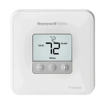
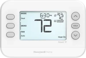
The LCD provides current room temperature, temperature setpoint, time, system status, schedule information, and alert messages. Physical buttons provide access to operating modes, fan settings, temperature adjustments, and configuration menus.
The thermostat uses two AA alkaline batteries, which are required even when a C-wire is connected. Installation uses the included UWP wall plate and push-in wiring terminals.
X2P Thermostat Models and HVAC Compatibility
The X2P Series includes three model groups.
| Model Numbers | Supported System Configuration |
| RTH20B / RTHC20B | 1 Heating Stage / 1 Cooling Stage (1H/1C) |
| RTH21B / RTHC21B | 1 Heating Stage / 1 Cooling Stage (1H/1C) |
| RTH22B / RTHC22B | 2 Heating Stages / 2 Cooling Stages for conventional systems, or 2 Heating Stages / 1 Cooling Stage for heat pumps |
Conventional Heating and Cooling Systems
The thermostat supports conventional heating and cooling configurations within the limits of the selected model.
The RTH22B/RTHC22B models support two-stage heating and two-stage cooling in conventional applications.
Heat Pump Systems
The RTH22B/RTHC22B models support the specified two-heat, one-cool heat pump configuration.
For compatible heat pump applications, auxiliary heating must be connected to the AUX terminal.
The thermostat supports electric auxiliary backup heat. Heat pumps using gas or oil backup heating are not supported.
Line-Voltage Systems
The X2P is not compatible with line-voltage thermostat systems operating at 120V or 240V.
A system with thick black wires connected using wire nuts, or a thermostat rated at 120V or higher, must not be connected to the X2P.
Technical Specifications
| Specification | Details |
| Brand | Honeywell Home |
| Product Name | X2P Programmable Thermostat |
| Product Type | Programmable HVAC Thermostat |
| Model Numbers | RTH20B, RTHC20B, RTH21B, RTHC21B, RTH22B, RTHC22B |
| Display | LCD |
| Controls | Physical Buttons |
| Power Source | Two AA Alkaline Batteries |
| C-Wire Requirement | Does Not Replace Battery Power |
| Mounting System | UWP Wall Plate |
| System Modes | Auto, Heat, Cool, Emergency Heat, Off, Depending on Configuration |
| Fan Modes | Auto, On, Circulate |
| Circulate Fan Operation | Approximately 33% of the Time |
| Scheduling Periods | Wake, Away, Home, Sleep |
| Scheduling Options | 1-Week, 5-2, 5-1-1, and 7-Day, Depending on Model |
| Smart Response | Configurable |
| Compressor Protection | Built-In |
| Temperature Display | Fahrenheit or Celsius |
| Clock Format | 12-Hour or 24-Hour |
| Daylight Saving Time | Configurable |
| Heating Setpoint Range | 32–90°F (0–32°C) |
| Cooling Setpoint Range | 50–99°F (10–37°C) |
| Minimum Heating Setpoint Configuration | 32–50°F (0–10°C), Default 40°F (4.5°C) |
| Air Filter Reminder | Configurable |
| Alert Codes | 405, 407, 170, 171, 173 |
| Warranty | 1-Year Limited Warranty |
| Manufacturer | Resideo Technologies, Inc. |
Available functions depend on the model, connected equipment, and installer configuration.
What’s Included in the Box
The X2P thermostat package includes the installation components shown in the product guide.
| Included Component | Purpose |
| X2P Thermostat | Controls compatible heating and cooling equipment. |
| UWP Wall Plate | Provides wall mounting and wiring connections. |
| Screws | Secure the wall plate to the wall. |
| Wall Anchors | Support the mounting screws. |
| Installation Literature | Provides installation and operating instructions. |
| Replacement Accent Piece | Changes the appearance of supported models. |
The RTH21B/RTHC21B and RTH22B/RTHC22B models include white and gray accent-piece options.
Thermostat Parts, Buttons, and LCD Display
The X2P has physical buttons on both sides of the LCD.
The left-side buttons provide system mode, menu, and fan controls. The right-side controls provide temperature adjustment, menu navigation, and Hold operation.
Button Functions
| Button | Function |
| MODE | Cycles through available system operating modes. |
| MENU | Opens configuration and scheduling options. |
| FAN | Changes the fan operating mode. |
| Up Arrow (∧) | Increases the temperature setpoint or changes menu values. |
| Down Arrow (∨) | Decreases the temperature setpoint or changes menu values. |
| HOLD | Accesses schedule override options. |
| SELECT | Confirms a menu selection. |
| NEXT | Advances to the next setting. |
| SAVE / SAVE & EXIT | Stores changes. |
| EXIT | Returns from a menu. |
The functions displayed beside some buttons change according to the menu being used.
LCD Display Guide
| Display Area | Meaning |
| Time | Current clock time. |
| Mode | Selected HVAC operating mode. |
| Set To | Desired indoor temperature. |
| Indoor | Current measured room temperature. |
| Fan | Selected fan mode. |
| Schedule Information | Current schedule or Hold status. |
| Heat On | Heating equipment is being requested to operate. |
| Cool On | Cooling equipment is being requested to operate. |
| Aux Heat On | Auxiliary heating is operating. |
Current Temperature vs. Set Temperature
The large temperature reading represents the current indoor temperature.
The smaller setpoint reading indicates the desired temperature.
Pressing the Up or Down arrow allows the setpoint to be changed.
Customizable Accent Piece
Supported models include replacement accent pieces.
To replace the accent piece:
- Grasp the existing accent piece.
- Pull it away from the thermostat.
- Position the replacement piece.
- Snap the new piece into place.
Important Safety Instructions
Incorrect thermostat wiring or configuration can cause unintended operation of heating and cooling equipment.
Such problems may result in property damage, personal injury, or death.
Electrical Safety
Power to the heating and cooling equipment must be switched off before installation.
- Turn off the appropriate circuit breaker or equipment power switch.
- Check whether the heating and cooling systems use separate breakers.
- Confirm that the equipment is not operating before disconnecting wiring.
- Do not handle exposed wiring while the system is energized.
Warning: Electrical power must be disconnected before installation to prevent electric shock and equipment damage.
Wiring and Equipment Safety
- Identify the HVAC system before connecting wires.
- Record the existing terminal connections before removing the previous thermostat.
- Do not assume that wire colors identify their functions.
- Connect wires according to the terminal labels and appropriate system wiring diagram.
- Do not connect the X2P to a 120V or 240V line-voltage system.
- Do not use the W terminal for heat pump applications.
- Use the AUX terminal for supported auxiliary heat connections.
- Contact a qualified HVAC contractor when the wiring configuration is uncertain.
Compressor Protection During Testing
Compressor protection is bypassed during equipment testing.
Rapidly switching the compressor on and off during testing can damage the equipment.
The compressor must not be cycled quickly.
Mercury Disposal Warning
If the thermostat replaces an older control containing mercury in a sealed tube, the old control must not be discarded in household trash.
Contact the local waste management authority for recycling and disposal instructions.
Tools Required for Installation
Required Tools
| Tool | Purpose |
| Phillips Screwdriver | Installing and removing screws |
| Small Flat-Head Screwdriver | Releasing wiring connections |
| Pencil | Marking holes and holding wires |
| Level | Positioning the wall plate |
Additional Tools That May Be Needed
- Wire stripper
- Needle-nose pliers
- Drill and drill bit
Before Installation
The existing thermostat and HVAC wiring must be checked before installation begins.
Step 1: Turn Off HVAC Power
Turn off the circuit breaker or power switch controlling the heating and cooling equipment.
Some systems use separate breakers for heating and cooling.
Step 2: Verify That the System Is Off
Using the old thermostat:
- Select Heat or Cool.
- In Heat mode, set the temperature above the current room temperature.
- In Cool mode, set the temperature below the current room temperature.
- Wait up to five minutes.
If the heating or cooling equipment does not start, the power is considered off for the procedure.
This step can be skipped if the old digital thermostat already has a blank display.
Step 3: Remove the Old Thermostat Faceplate
Most thermostat faceplates can be removed by gently pulling them away from the mounting plate.
Some faceplates use screws, buttons, or retaining clips.
Do not disconnect the wires at this stage.
Step 4: Check for Line-Voltage Wiring
Inspect the wiring for thick black wires connected with wire nuts.
Check whether the previous thermostat is rated at 120V or higher.
If either condition applies, the X2P is not compatible.
Step 5: Photograph the Existing Wiring
Take a clear photograph showing the connected wires and the letters beside their terminals.
The photograph should be used when connecting the new thermostat.
Step 6: Identify Jumper Wires
A jumper connects one terminal to another.
It may look like a small metal staple or a short piece of wire.
Record any existing jumpers.
The X2P does not require jumper wires.
Step 7: Record the R-Terminal Connections
Check whether the existing thermostat has wires connected to:
- R
- RH
- RC
Do not count jumper wires.
Step 8: Record the Remaining Wiring
Record the terminal letters and wire colors for all connected wires.
| Possible Existing Terminal | Record Wire Color |
| Y | As installed |
| Y2 | As installed |
| G | As installed |
| C | As installed |
| A or L/A | As installed |
| O/B | As installed |
| W2 or AUX | As installed |
| E | As installed |
| W | As installed |
| K | As installed |
Only the terminals actually used by the existing installation need to be recorded.
Step 9: Disconnect the Old Wires
- Release each wire using a screwdriver.
- Label each wire according to the terminal letter.
- Disconnect the wire.
- Repeat for all connected wires.
- Remove the old wall plate.
To prevent the wires from falling into the wall, they can be wrapped around a pencil.
How to Install the UWP Wall Plate
The X2P uses a Universal Wiring Plate (UWP) for mounting and connecting HVAC wiring.
Step 1: Insert the Wires Through the Wall Plate
Open the UWP wall plate.
Pass the wire bundle through the opening at the back of the plate.
Make sure that approximately ¼–⅜ inch of conductor is exposed at the ends of the wires.
At least ¼ inch of exposed conductor is needed for insertion into the terminals.
Step 2: Position the Wall Plate
Center the UWP over the wall opening.
Use a level to align it horizontally.
Step 3: Mark the Mounting Holes
Use the UWP as a template.
Mark the required screw locations using a pencil.
Step 4: Drill the Holes
Use a 3/16-inch drill bit to make holes for the supplied wall anchors.
Step 5: Install the Wall Anchors
Insert the wall anchors into the holes.
Carefully tap them with a hammer until they are flush with the wall.
How to Wire the X2P Thermostat
The UWP wall plate has more terminals than most installations require.
Only the terminals appropriate for the connected HVAC system should be used.
Warning: Incorrect wiring or system configuration can cause dangerous or unintended HVAC operation. A qualified HVAC professional should handle installations where the equipment type or wiring cannot be identified confidently.
Step 1: Set the R Slider Switch
The R slider switch must match the number of R wires recorded from the old thermostat.
If There Is One R Wire
For a single wire previously connected to R, Rh, or Rc:
- Move the R slider switch to the UP position.
- Insert the wire into the R terminal.
If There Are Two R Wires
For separate R or Rh and Rc wires:
- Move the R slider switch to the DOWN position.
- Connect the Rc wire to the Rc terminal.
- Connect the R or Rh wire to the R terminal.
R Slider Position Chart
| Existing Wiring | R Slider Position | Connections |
| One R, Rh, or Rc wire | UP | Connect the wire to R. |
| Two wires: R/Rh and Rc | DOWN | Connect Rc to Rc and R/Rh to R. |
Step 2: Connect the Remaining Wires
- Refer to the photograph and wiring notes from the old thermostat.
- Find the corresponding terminals on the UWP.
- Press the appropriate terminal tab if necessary.
- Insert each wire into the inner hole of its terminal.
- Connect only one wire per terminal.
- Gently pull each wire to confirm that it is secure.
To release a wire, press the corresponding terminal tab.
Step 3: Verify the Connections
Compare the completed wiring with the photograph taken before removing the old thermostat.
Make sure that the terminal connections match the required configuration.
Step 4: Secure the UWP
Mount the UWP using all three supplied #6 × 1½-inch screws.
Close the UWP door after the wiring is complete.
Alternate Wiring for Conventional Systems
Additional wiring instructions apply when the old thermostat labels do not directly match the UWP terminals.
Separate R and Rc Wires
If both R and Rc wires must be connected, place the R slider in the DOWN position.
Existing R and RH Wires
If the old thermostat had separate R and RH wires:
- Set the R slider to DOWN.
- Connect the old R wire to the new Rc terminal.
- Connect the old RH wire to the new R terminal.
Existing C or C1 Wires
| Existing Wiring | Required Action |
| One C or C1 wire | Connect it to C. |
| Two C or C1 wires | Insulate each separately with electrical tape; do not connect them. |
Important: The C terminal does not power the X2P thermostat display or operation. Two AA alkaline batteries are always required.
Alternate Wiring for Heat Pumps
Heat pump installations have additional wiring requirements.
R Slider Position
For the documented heat pump wiring arrangement, keep the R slider in the UP position for one R wire.
Existing V and VR Wires
If the old thermostat has both V and VR wires, stop the installation and contact a qualified contractor.
Separate O and B Wires
If the previous thermostat has separate O and B wires, the guide directs the B wire to the C terminal.
If another wire is already connected to C, stop and contact a qualified contractor.
Existing Y1, W1, and W2 Wires
If the old thermostat has Y1, W1, and W2 wires, stop the installation and contact a qualified contractor.
Auxiliary Heat Wiring
For heat pump applications:
- Do not use W.
- Auxiliary heating must connect to AUX.
- An existing Aux or E wire connects to AUX on the new thermostat.
Heat Pump Fault Alert
The X2P does not support the heat pump fault alert associated with the L/A terminal.
If this feature is required, a qualified contractor should be contacted about a compatible replacement model.
Installing the Batteries and Attaching the Thermostat
Step 1: Install Two AA Batteries
Insert two fresh AA alkaline batteries into the compartments on the back of the thermostat.
Follow the polarity markings shown in the battery compartment.
Step 2: Attach the Thermostat
Align the thermostat with the installed UWP wall plate.
Press the thermostat firmly into place until it snaps onto the mounting plate.
Step 3: Restore Electrical Power
Turn on the circuit breaker or equipment power switch controlling the heating and cooling system.
The thermostat is now ready for configuration.
How to Set the Time and Date
During initial setup, the date begins flashing after the thermostat is powered.
The time and date can also be adjusted through the menu.
How to Set the Time
- Press MENU.
- Use the Up or Down arrow until TIME appears.
- Press SELECT.
- Choose a 12-hour or 24-hour clock format.
- Press NEXT.
- Adjust the hour using the arrow buttons.
- Press NEXT.
- Adjust the minutes.
- Complete the setting and return to the Home screen.
How to Set the Date
- Press MENU.
- Use the arrows to select DATE.
- Press SELECT.
- Adjust the year.
- Press NEXT.
- Adjust the month.
- Press NEXT.
- Adjust the date.
- Press SAVE and then EXIT.
Installer Setup and Configuration
The X2P includes an Installer Setup menu, identified as ISU.
During the first installation, the thermostat enters the ISU menu after the time and date are configured.
Installer settings determine the thermostat’s equipment compatibility and available operating features.
How to Open Installer Setup
- Press and hold the bottom-left button and the Up arrow simultaneously for five seconds.
- The Installer Setup screen appears.
- The ISU number appears on the left.
- The current setting appears on the right.
- Use the arrow buttons to change the displayed setting.
- Press NEXT to move to the next ISU option.
- Press SAVE & EXIT to store the settings and return to the Home screen.
Incorrect installer settings can cause unintended equipment operation. Equipment-related settings must match the connected HVAC system.
Installer Setup Options (ISU)
The available settings depend on the thermostat model and system configuration.
| ISU Number | Setting | Available Options |
| 1040 | Scheduling Options | 1-week, 5-2, 5-1-1, 7-day |
| 1050 | Temperature Scale | Fahrenheit or Celsius |
| 2000 | Heating System Type | Conventional Forced Air, Heat Pump, Radiant Heat, Cool Only |
| 2010 | Heating Equipment Type | Gas, Oil, Electric, Hot Water Fan Coil, Radiant Hot Water, Steam |
| 2060 | Reversing Valve O/B | O on Cool or B on Heat |
| 2070 | Cooling/Compressor Stages | 0, 1, or 2 according to equipment |
| 2071 | Heating/Backup Heat Stages | Heating stages 1 or 2; backup heat 0 or 1 where supported |
| 2180 | Auxiliary Backup Heat Type | Electric Forced Air |
| 3000 | Automatic Changeover | Hidden or Enabled |
| 4090 | Smart Response | No or Yes |
| 4103 | Minimum Heating Setpoint | 32–50°F |
| 7110 | Air Filter Replacement Reminder | Off, runtime-based, or calendar-based |
| 14005 | Idle Screen Selection | Minimum, Setpoint, or Maximum Information |
| 14010 | Clock Format | 12-hour or 24-hour |
| 14015 | Daylight Saving Time | Off or On |
Scheduling Options — ISU 1040
| Value | Schedule Type |
| 1 | 1-week: all days use the same schedule |
| 2 | 5-2: separate weekdays and weekend |
| 3 | 5-1-1: weekdays, Saturday, and Sunday separately |
| 4 | 7-day: each day can be scheduled individually |
The RTH20B is limited to the 5-2 scheduling setting.
Heating System Type — ISU 2000
The available values include:
| Value | System Type |
| 1 | Conventional Forced Air |
| 2 | Heat Pump |
| 3 | Radiant Heat / Boiler |
| 5 | Cool Only |
Heating Equipment Type — ISU 2010
The equipment selections include:
| Value | Equipment |
| 1 | Standard-Efficiency Gas Forced Air |
| 2 | High-Efficiency Gas Forced Air |
| 3 | Oil Forced Air |
| 4 | Electric Forced Air |
| 5 | Hot Water Fan Coil |
| 9 | Hot Water Radiant Heat |
| 12 | Steam |
Available choices depend on the heating system type.
Heat Pump Reversing Valve — ISU 2060
| Value | Setting |
| 0 | O: reversing valve energized during cooling |
| 1 | B: reversing valve energized during heating |
The correct selection depends on the heat pump equipment.
Cooling and Heating Stages — ISU 2070 and 2071
ISU 2070 configures cooling or compressor stages.
The available stage values are 0, 1, or 2, subject to the model and connected system.
Only one compressor stage is supported for heat pumps.
ISU 2071 configures the number of heating stages and available backup heating stages.
Auxiliary Backup Heat — ISU 2180
Value 31 identifies Electric Forced Air auxiliary heat.
The thermostat supports electric backup heat for the applicable heat pump configurations.
Gas or oil backup heating is not supported.
Automatic Changeover — ISU 3000
| Value | Function |
| 0 | Hidden: manual mode selection only |
| 1 | Enabled: automatic switching between heating and cooling |
In Auto mode, the thermostat switches between heating and cooling to maintain the desired indoor temperature.
The manufacturer does not recommend this option when outdoor winter temperatures frequently remain below 50°F (10°C).
Smart Response — ISU 4090
| Value | Function |
| 0 | Disabled |
| 1 | Enabled |
When enabled, Smart Response can start heating or cooling before a scheduled period to reach the desired temperature at the programmed time.
Minimum Heating Setpoint — ISU 4103
The minimum heating setpoint can be configured from 32°F to 50°F.
The default setting is 40°F (4.5°C).
The manufacturer warns against setting the minimum below 40°F (4.5°C) where pipes may be at risk of freezing.
Air Filter Reminder — ISU 7110
The filter reminder supports runtime-based or calendar-based intervals.
| Reminder Type | Available Intervals |
| Runtime Days | 10, 20, 30, 45, 60, 90, 120, or 150 days |
| Calendar Days | 30, 45, 60, or 75 days |
| Calendar Months | 3, 4, 5, 6, 9, 12, or 15 months |
| Off | Reminder disabled |
Runtime days count only while heating, cooling, or fan operation is active.
Idle Screen Selection — ISU 14005
| Value | Display |
| 0 | Minimum information |
| 1 | Temperature setpoint |
| 2 | Maximum information |
Clock Format — ISU 14010
Select either the 12-hour or 24-hour clock format.
Daylight Saving Time — ISU 14015
| Value | Function |
| 0 | Off |
| 1 | On |
How to Change System Modes
The X2P provides several system operating modes.
Changing the System Mode
- Press MODE.
- The thermostat advances to the next available operating mode.
- Continue pressing MODE until the required mode appears.
System Mode Guide
| Mode | Function |
| AUTO | Automatically changes between heating and cooling when configured. |
| HEAT | Selects heating operation. |
| COOL | Selects cooling operation. |
| EM HEAT | Selects emergency heat when supported. |
| OFF | Turns off heating and cooling control. |
The available modes depend on the model and HVAC configuration.
How to Change Fan Settings
The FAN button changes the fan operating mode.
Changing the Fan Mode
- Press FAN.
- Continue pressing until the desired setting appears.
Fan Mode Guide
| Fan Mode | Operation |
| AUTO | Fan operates when the heating or cooling system is running. |
| ON | Fan operates continuously. |
| CIRC | Fan runs approximately 33% of the time to circulate air. |
Available fan modes vary according to system settings.
How to Program a Heating and Cooling Schedule
The X2P can use up to four daily temperature periods.
Each period can have its own start time and heating and cooling setpoints.
Schedule Periods
| Period | Purpose |
| WAKE | Morning temperature before leaving home |
| AWAY | Energy-saving temperature while away |
| HOME | Comfortable temperature after returning home |
| SLEEP | Overnight temperature |
Recommended Schedule Settings
The manufacturer provides the following example schedule.
| Period | Start Time | Heat | Cool |
| Wake | 6:00 AM | 70°F | 78°F |
| Away | 8:00 AM | 62°F | 85°F |
| Home | 6:00 PM | 70°F | 78°F |
| Sleep | 10:00 PM | 62°F | 82°F |
These settings are intended to reduce heating and cooling expenses.
How to Enable a Schedule
- Press MENU.
- Use the Up or Down arrow until SCHED appears.
- Select ON to activate scheduling.
- Press SELECT to edit the schedule.
Selecting OFF disables the schedule.
How to Edit a Schedule
- Open the SCHED menu.
- Select the day or group of days to edit.
- Press SELECT.
- When WAKE flashes, press NEXT.
- Select ON or OFF for that period.
- Press NEXT.
- Adjust the start time.
- Press NEXT.
- Adjust the heating setpoint.
- Press NEXT.
- Adjust the cooling setpoint.
- Press NEXT.
- Repeat for Away, Home, and Sleep.
- Repeat for other days or day groups as required.
- Press SAVE & EXIT.
A schedule period set to OFF is disabled.
Smart Response and Active Recovery
Smart Response allows the thermostat to learn how long the heating or cooling equipment takes to reach the scheduled temperature.
The thermostat can then start the equipment before the scheduled time.
Active Recovery Example
If the Wake period is scheduled for 6:00 AM with a heating setpoint of 70°F, the thermostat may start heating before 6:00 AM.
This allows the room to reach approximately 70°F at the scheduled time.
While operating ahead of the schedule, the display shows:
Active Recovery
This message indicates that Smart Response is preparing the home for the upcoming scheduled period.
How to Temporarily Override the Schedule
A temporary override changes the desired temperature until the next scheduled period begins.
Setting a Temporary Hold
- Press the Up or Down arrow.
- Adjust the temperature to the desired setpoint.
- Press SAVE or allow the display to return to the Home screen.
The selected temperature remains in effect until the next scheduled period.
Canceling a Temporary Hold
Press and release HOLD until CANCEL HOLD is selected.
The thermostat resumes its scheduled operation.
How to Set a Permanent Hold
A permanent Hold keeps the selected temperature instead of allowing the schedule to change it.
Setting a Permanent Hold
- Press the Up or Down arrow.
- Adjust the temperature to the desired setting.
- Press and release HOLD until HOLD PERMANANTLY appears.
- Press SAVE or allow the display to return to the Home screen.
Canceling a Permanent Hold
Press and release HOLD until CANCEL HOLD is selected.
The thermostat then resumes its programmed schedule.
Reminders and Notifications
The thermostat displays a reminder icon when a reminder is active.
How to View a Reminder
- Press MENU.
- Use the Up or Down arrow until the active reminder appears.
- Press SELECT.
- Read the scrolling reminder message.
How to Dismiss a Reminder
Press DISMISS to reset the reminder.
Press EXIT to return to the Home screen without resetting it.
If multiple reminders are active, press NEXT to review them.
Thermostat Alert Codes and Messages
When an alert is active, an alert icon appears near the bottom of the display.
The alert menu allows the associated alert number to be viewed.
How to View an Alert
- Press MENU.
- Use the arrows to locate the active alert.
- Press SELECT.
- Read the displayed alert number.
- Press NEXT to review additional alerts, if present.
- Press EXIT to return to the Home screen.
Active alerts cannot be dismissed in the same way as reminders.
Alert Code Chart
| Alert Code | Meaning | Recommended Action |
| 405 | Thermostat batteries are low. | Replace the batteries. |
| 407 | Thermostat batteries are critically low. | Replace the batteries. |
| 170 | Thermostat memory failure. | Professional service may be required. |
| 171 | Time and date require setting. | Set the time and date. |
| 173 | Internal temperature sensor error. | Professional service may be required. |
Some alerts can be resolved by replacing batteries or correcting settings.
Other alerts may require an HVAC service professional.
How to Replace the Thermostat Batteries
The X2P requires two AA alkaline batteries.
The thermostat displays a warning when the batteries need replacement.
Battery Replacement Instructions
- Grasp the thermostat body.
- Gently pull it away from the UWP mounting plate.
- Remove the old batteries.
- Insert two fresh AA alkaline batteries.
- Follow the polarity markings.
- Align the thermostat with the mounting plate.
- Push gently until it snaps into place.
Battery Requirements
| Item | Requirement |
| Battery Type | AA Alkaline |
| Quantity | 2 |
| Replacement Trigger | Low or critically low battery alert |
| C-Wire | Does not eliminate the battery requirement |
The thermostat requires batteries for display and operation even when a C-wire is connected.
Built-In Compressor Protection
The X2P includes a compressor protection feature that prevents the compressor from restarting too soon after shutdown.
Restarting too quickly can damage the compressor.
Waiting for Equipment Message
During the protection delay, the thermostat may display:
Waiting For Equipment
The message appears below the room temperature reading.
What Happens During the Delay?
The thermostat temporarily delays equipment operation.
Once the safe waiting period has passed, the message disappears.
The display then shows Heat On or Cool On when the appropriate equipment is operating.
The troubleshooting instructions recommend waiting approximately five minutes.
Troubleshooting Guide
The following procedures address common thermostat and HVAC operating problems.
Quick Troubleshooting Table
| Problem | Possible Cause | Recommended Action |
| Display is blank | Batteries are missing, depleted, or incorrectly installed. | Install fresh AA alkaline batteries correctly. |
| Heating does not start | Incorrect mode, temperature setting, power issue, or protection delay. | Check mode, setpoint, breaker, and equipment power. |
| Cooling does not start | Incorrect mode, temperature setting, power issue, or protection delay. | Check operating settings and wait for compressor protection. |
| Heat operates during cooling | Heat pump wiring or reversing-valve configuration problem. | Check the wiring and ISU 2060. |
| Heating operates without a call | Incorrect wiring or shorted wires. | Have the wiring and control connections checked. |
| Temperature cannot be adjusted to the desired value | Operating mode or configured setpoint restriction. | Check the mode and installer limits. |
| Waiting For Equipment | Compressor protection is active. | Wait for the safe restart delay. |
Thermostat Display Is Blank
Possible Cause: Batteries are missing, depleted, or installed incorrectly.
Recommended Action
- Remove the thermostat from the wall plate.
- Check the battery installation.
- Install fresh AA alkaline batteries.
- Reattach the thermostat.
Heating or Cooling Does Not Run
The thermostat displays equipment status when it requests heating or cooling.
- HEAT ON indicates a heating call.
- COOL ON indicates a cooling call.
- WAITING FOR EQUIPMENT indicates a compressor protection delay.
Recommended Actions
- Check the selected operating mode.
- Check the temperature setpoint.
- Compare the setpoint with the actual room temperature.
- If Waiting For Equipment appears, wait approximately five minutes.
- Check the circuit breaker.
- Confirm that the heating and cooling equipment power switch is on.
- Make sure the furnace door is securely closed.
Heat or Auxiliary Heat Runs During Cooling
Possible causes include heat pump wiring and reversing-valve configuration.
Recommended Checks
- Confirm that no wire is connected to W for a heat pump.
- Verify that ISU 2060 matches the equipment’s reversing-valve operation.
- Check whether exposed wire sections are causing a short circuit at the UWP.
Because these checks involve HVAC wiring, a qualified professional should investigate uncertain connections.
Heat or Auxiliary Heat Runs Without a Heating Call
Recommended Checks
- Confirm that the display is not showing HEAT ON, COOL ON, or AUX HEAT ON.
- Check for a W-terminal connection in heat pump installations.
- Check for shorted wires or exposed conductors at the UWP.
Electrical power must be disconnected before wiring is inspected.
Cannot Change the Temperature Setpoint
The operating mode determines the available temperature range.
| Mode | Available Setpoint Range |
| Heat | 32–90°F (0–32°C) |
| Emergency Heat | 32–90°F (0–32°C) |
| Cool | 50–99°F (10–37°C) |
If the temperature can be adjusted but cannot reach the full available range, an installer-configured maximum heating or minimum cooling limit may be active.
Waiting for Equipment Does Not Immediately Clear
This message indicates that compressor protection is active.
The thermostat delays compressor operation to prevent equipment damage.
Wait approximately five minutes.
If heating or cooling still does not operate, check the system mode, setpoint, room temperature, and equipment power.
Regulatory and Compliance Information
FCC Regulations
The thermostat complies with Part 15 of the FCC Rules.
Operation is subject to two conditions:
- The device must not cause harmful interference.
- The device must accept interference received, including interference that may cause undesired operation.
Unapproved changes or modifications may void the user’s authority to operate the equipment.
Additional information is available at:
https://resideo.info/fcc-statement
Canadian IC Regulations
The thermostat contains licence-exempt transmitters or receivers that comply with applicable Innovation, Science and Economic Development Canada RSS requirements.
The device must not cause interference and must accept interference that may affect its operation.
Disposal and Recycling Instructions
Mercury-Containing Thermostat Disposal
An older thermostat containing mercury in a sealed tube must not be discarded in ordinary household trash.
Contact the local waste management authority for proper recycling and disposal instructions.
Electronic Waste Disposal
The X2P thermostat must not be disposed of with normal household waste.
At the end of its service life, the device should be taken to an authorized collection center or electronics recycler.
Proper disposal helps reduce potential environmental and health impacts.
Warranty Information
The Honeywell Home X2P Programmable Thermostat is covered by a 1-year limited warranty.
Warranty Details
The manufacturer provides warranty terms at:
How to Request a Printed Warranty
A printed warranty copy can be requested from Resideo Customer Care.
Telephone: 1-800-633-3991
The manufacturer will mail the printed warranty free of charge.
Customer Support Information
The X2P Programmable Thermostat is manufactured by Resideo Technologies, Inc. and its affiliates.
The Honeywell Home trademark is used under license from Honeywell International Inc.
| Contact Type | Details |
| Brand | Honeywell Home |
| Manufacturer | Resideo Technologies, Inc. |
| Customer Care | 1-800-633-3991 |
| Manufacturer Contact | 1-800-468-1502 |
| Product Support Website | https://www.honeywellhome.com |
| Manufacturer Website | https://www.resideo.com |
| Warranty Information | https://resideo.info/US-Warranty-THERMOSTAT |
| FCC Information | https://resideo.info/fcc-statement |
Manufacturer Address
Resideo Technologies, Inc.
Scottsdale, AZ 85254
United States
When to Contact a Qualified HVAC Professional
Professional assistance is appropriate when:
- The HVAC system type cannot be identified.
- Existing wiring does not match the supported configurations.
- The system has unsupported heat pump backup heating.
- The thermostat displays an internal memory or sensor alert.
- Heating or cooling operates unexpectedly.
- The installation requires electrical or system configuration changes.
Frequently Asked Questions
1. How do I install the Honeywell Home X2P Programmable Thermostat?
Turn off power to the heating and cooling equipment, remove the old thermostat faceplate, photograph the existing wiring, and label each wire by its terminal letter. Install the UWP wall plate, set the R slider according to the existing R wires, and connect the wires to their matching terminals.
Install two AA alkaline batteries, attach the thermostat to the wall plate, restore power, and complete the initial configuration. If the system type or wiring is uncertain, installation should be performed by a qualified HVAC professional.
2. Does the Honeywell X2P thermostat need batteries if it has a C-wire?
Yes. The X2P requires two AA alkaline batteries for display and operation. The C terminal does not provide power for the thermostat’s display or controls. Fresh batteries must be installed even when a C-wire is connected.
3. How do I set a heating and cooling schedule on the Honeywell X2P?
Press MENU and use the arrow buttons to select SCHED. Turn scheduling ON and press SELECT. Choose the days or day group to edit, then configure the Wake, Away, Home, and Sleep periods. Each period can have its own start time and heating and cooling setpoints. Press SAVE & EXIT after completing the settings.
4. How do I turn off the programmed schedule?
Press MENU and navigate to SCHED. Use the arrow buttons to select OFF, then exit the menu. With scheduling disabled, the thermostat no longer follows its programmed daily temperature periods.
5. How do I put the Honeywell X2P thermostat on permanent Hold?
Use the Up or Down arrow to select the desired temperature. Press and release HOLD until the permanent Hold option appears. Press SAVE or allow the screen to return to the Home display. To resume the programmed schedule, press HOLD until CANCEL HOLD is selected.
6. What does Waiting For Equipment mean on the Honeywell X2P?
The message indicates that built-in compressor protection is active. The thermostat temporarily delays compressor operation to prevent damage caused by restarting too quickly. The manufacturer recommends waiting approximately five minutes. The message disappears when the safe waiting period has ended.
7. What do Honeywell X2P thermostat alert codes 405, 407, 170, 171, and 173 mean?
Alert 405 indicates low batteries, while 407 indicates critically low batteries. Both require battery replacement. Alert 170 indicates an internal thermostat memory problem, 171 indicates that the time and date must be set, and 173 indicates a built-in temperature sensor error.
8. Why is the Honeywell X2P thermostat display blank or not turning on?
The most common issue identified in the manual is missing, depleted, or incorrectly installed AA batteries. Remove the thermostat from the wall plate and install two fresh AA alkaline batteries according to the polarity markings. Reattach the thermostat securely.
The display requires batteries even when the C terminal is connected.