| Field | Details |
| Document Title | T6 Pro Programmable Thermostat Installation Instructions |
| Document Type | Installation Instructions |
| Brand Name | Honeywell Home |
| Product Name | T6 Pro Programmable Thermostat |
| Model Number(s) | T6 Pro series; TH6320U, TH6220U |
| PDF File Size | 4.19 MB |
| Total Number of Pages | 36 |
| Languages Covered | English, French, Spanish |
Honeywell Home T6 Pro Programmable Thermostat
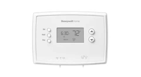
The Honeywell Home T6 Pro is a programmable digital thermostat designed to control compatible residential heating and cooling systems. It supports conventional forced-air heating, heat pumps, radiant heating, and other supported HVAC configurations according to the thermostat model and installer settings.
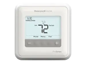
The thermostat features a digital display, five control buttons, configurable heating and cooling modes, fan settings, temperature limits, and programmable scheduling options.
The T6 Pro can operate using two AA batteries or a compatible 24 VAC connection. When the thermostat receives power through the R and C terminals, batteries can serve as backup power.
The thermostat uses the UWP mounting system, which provides labeled wiring terminals and an integrated R/Rc slider tab for single-transformer and two-transformer installations.
Installer Setup (ISU) allows the thermostat to be configured for the connected equipment. Available settings include heating system type, heating and cooling stages, fan control, heat pump changeover valve operation, compressor protection, temperature limits, scheduling, and display options.
The T6 Pro also includes an Installer System Test for checking heating, cooling, fan operation, and supported emergency heating functions after installation.
Product Overview and Features
| Feature | Description |
| Product Type | Programmable HVAC thermostat |
| Digital Display | Shows temperature, system mode, and operating information |
| UWP Mounting System | Provides wall mounting and wiring terminals |
| Power Options | 24 VAC connection or two AA batteries |
| R/Rc Slider Tab | Configures single-transformer or two-transformer systems |
| Heating Control | Supports compatible heating equipment |
| Cooling Control | Supports compatible cooling equipment |
| Heat Pump Control | Supports supported heat pump configurations |
| Emergency Heat | Available on applicable configurations |
| System Modes | Auto, Heat, Cool, Em Heat, Off |
| Fan Modes | Auto, On, Circ |
| Programmable Scheduling | Non-programmable, 5-2, 5-1-1, or 7-day options |
| Temperature Units | Fahrenheit or Celsius |
| Compressor Protection | Adjustable compressor restart delay |
| Adaptive Intelligent Recovery | Starts heating or cooling early to reach scheduled temperature |
| Installer Setup | Advanced equipment configuration menu |
| Installer System Test | Checks individual heating, cooling, and fan functions |
| Air Filter Reminders | Supports up to two configurable filter reminders |
| Backlight Settings | On-demand or continuous illumination |
| Daylight Saving Time | Configurable clock adjustment |
What’s Included in the Box
The Honeywell T6 Pro package includes the following components.
| Item | Quantity or Details |
| T6 Pro Thermostat | 1 |
| UWP Mounting System | 1 |
| Honeywell Standard Installation Adapter | J-box adapter |
| Honeywell Decorative Cover Plate | Small |
| Screws and Anchors | Included |
| AA Batteries | 2 |
| Installation Instructions and User Guide | Included |
Decorative Cover Plate Dimensions
| Measurement | Size |
| Width | 4-49/64 inches (121 mm) |
| Height | 4-49/64 inches (121 mm) |
| Depth | 11/32 inch (9 mm) |
The cover plate is intended for installations involving an electrical junction box or where a larger mounting surface is needed to cover marks left by a previous thermostat.
Technical Specifications
General Specifications
| Specification | Details |
| Product Series | T6 Pro |
| Product Type | Programmable Thermostat |
| Main Power | 24 VAC through compatible thermostat wiring |
| Battery Power | 2 AA batteries |
| Recommended Thermostat Wire | 18–22 AWG |
| Shielded Thermostat Cable | Not required |
| Heating Setpoint Range | 40–90°F (4.5–32°C) |
| Cooling Setpoint Range | 50–99°F (10–37°C) |
| Working Ambient Temperature | 32–120°F (0–48.9°C) |
| Operating Ambient Temperature | 37–102°F (2.8–38.9°C) |
| Shipping Temperature | -20–120°F (-28.9–48.9°C) |
| Operating Relative Humidity | 5–90%, non-condensing |
| Thermostat Height | 4-1/16 inches (103.5 mm) |
| Thermostat Width | 4-1/16 inches (103.5 mm) |
| Thermostat Depth | 1-5/32 inches (29 mm) |
| Clock Format | 12-hour or 24-hour |
| Temperature Display | Fahrenheit or Celsius |
| Compressor Protection Adjustment | Off or 1–5 minutes |
| Fan Circulation Mode | Approximately 33% intermittent operation |
Electrical Ratings
| Terminal | Voltage | Running Current |
| W – Heating | 20–30 VAC | 0.02–1.0 A |
| Powerpile | 750 mV DC | 100 mA DC |
| W2 – Auxiliary/Second-Stage Heating | 20–30 VAC | 0.02–1.0 A |
| E – Emergency Heat | 20–30 VAC | 0.02–0.5 A |
| Y – Compressor Stage 1 | 20–30 VAC | 0.02–1.0 A |
| Y2 – Compressor Stage 2 | 20–30 VAC | 0.02–1.0 A |
| G – Fan | 20–30 VAC | 0.02–0.5 A |
| O/B – Changeover | 20–30 VAC | 0.02–0.5 A |
| L/A – Input | 20–30 VAC | 0.02–0.5 A |
The listed terminals and equipment stages are not available in every installation. Several advanced functions and second-stage connections apply specifically to models identified in the installation tables.
Important Safety Instructions
Electrical Shock Hazard
CAUTION: ELECTRICAL HAZARD
Electrical connections can cause electric shock or equipment damage.
Disconnect electrical power before beginning installation.
Power must be turned off at the breaker box or electrical switch before the thermostat mounting and wiring procedures begin.
Compressor Damage Hazard
CAUTION: EQUIPMENT DAMAGE HAZARD
The thermostat’s compressor protection is bypassed during installer testing.
Do not repeatedly start and stop the compressor in quick succession during testing.
Rapid compressor cycling can damage the heating or cooling equipment.
Mercury Disposal Warning
If the T6 Pro replaces a thermostat containing mercury in a sealed tube, the old thermostat must not be discarded with ordinary household waste.
Contact the local waste management authority for proper recycling and disposal instructions.
Electrical Installation Requirements
- Disconnect power before working on thermostat wiring.
- Use thermostat wire within the specified 18–22 AWG range.
- Provide the required power disconnect and overload protection.
- Configure the R/Rc slider according to the connected transformer arrangement.
- Connect only the terminals applicable to the heating and cooling system.
- Follow the correct wiring arrangement for the installed equipment.
Electrical wiring and installer configuration should be performed by a qualified HVAC technician or electrician.
Before Installation
The installer should identify the type of heating and cooling equipment and the existing thermostat wiring arrangement.
Installation Preparation
- Identify the connected HVAC system.
- Check whether it uses one transformer or separate heating and cooling transformers.
- Determine whether the thermostat will receive power through a C-wire or AA batteries.
- Prepare the UWP mounting system.
- Identify the wiring terminals needed for the equipment.
- Select whether the decorative cover plate is required.
- Disconnect electrical power before installation.
Supported Installation Arrangements
The wiring diagrams include configurations for:
- Conventional heating and cooling
- Heat-only equipment
- Heat-only systems with a fan
- Cool-only systems
- Series 20 heating systems
- Power-open zone valves
- Single-transformer heating and cooling
- Two-transformer heating and cooling
- Heat pump systems
- Auxiliary and emergency heating
- Multistage heating and cooling on supported models
- Dual-fuel equipment arrangements
Available wiring arrangements depend on the specific thermostat model.
Installing the Optional Decorative Cover Plate
The optional cover plate is used when mounting the thermostat to an electrical junction box or covering an existing wall finish gap.
When to Use the Cover Plate
Use the decorative cover plate when:
- The thermostat is mounted to an electrical junction box.
- The previous thermostat has left an exposed paint gap.
Installation Procedure
- Separate the junction box adapter from the decorative cover plate.
- Position the junction box adapter on the wall or electrical box.
- Use the appropriate mounting holes to align the adapter.
- Install the supplied mounting screws.
- Tighten the screws without overtightening.
- Confirm that the adapter plate is level.
- Attach the UWP mounting system to the top hook of the junction box adapter.
- Snap the bottom of the UWP into position.
- Attach the decorative cover plate to the junction box adapter.
Cover Plate Mounting Hardware
The adapter installation uses two supplied #6, 5/8-inch screws.
Do not overtighten the screws.
UWP Mounting System Installation
The UWP mounting system provides the physical mounting and electrical terminal connections for the thermostat.
Step 1: Disconnect Electrical Power
Turn off electrical power at the breaker box or switch before starting.
Step 2: Position the UWP
- Place the UWP against the wall.
- Level the mounting system.
- Mark the mounting hole positions.
Step 3: Drill the Mounting Holes
- Drill holes at the marked positions.
- For drywall, use 7/32-inch holes.
- Insert the supplied wall anchors.
- Tap the anchors gently into position using a hammer.
Step 4: Route the Thermostat Wires
- Open the UWP wiring door.
- Pass the thermostat wires through the wiring opening.
- Position the UWP over the wall anchors.
Step 5: Secure the UWP
- Insert the supplied mounting screws.
- Tighten the screws until the UWP no longer moves.
- Do not overtighten.
- Close the wiring door.
UWP Mounting Screws
The UWP installation uses three supplied #8, 1-1/2-inch screws.
Thermostat Power Options
The T6 Pro can receive power through a compatible 24 VAC connection or from AA batteries.
AC Power Connection
The thermostat uses the R and C terminals for primary AC power.
| Terminal | Function |
| R | 24 VAC power |
| C | 24 VAC common |
The C terminal is optional when batteries are installed, but the installation instructions recommend using the C connection.
Battery Power
Two AA batteries can provide:
- Primary thermostat power
- Backup power when AC power is connected
Installing the AA Batteries
- Locate the battery compartment on the back of the thermostat.
- Insert two AA batteries.
- Follow the positive and negative polarity markings.
Removing Wires From UWP Terminals
Wires can be released from the UWP by pressing the corresponding terminal tabs.
Power must be disconnected before modifying thermostat wiring.
Configuring the R/Rc Slider Tab
The UWP includes an integrated R/Rc slider tab.
This tab is used to configure the connection for one-transformer or two-transformer systems.
Single-Transformer System
If the installation has only one R wire connected to an R, Rc, or RH terminal:
Set the slider to the upper position marked for one wire.
Two-Transformer System
If the installation has:
- One wire connected to R
- Another wire connected to Rc
Set the slider to the lower position marked for two wires.
R/Rc Slider Settings
| Wiring Arrangement | Slider Position |
| One R wire | Up – 1 wire |
| Separate R and Rc wires | Down – 2 wires |
The slider tabs associated with the U terminals should remain in place for T6 Pro models.
UWP Wiring Terminal Guide
The UWP includes labeled terminals for heating, cooling, fan control, power, sensors, and other supported functions.
Wiring Terminal Functions
| Terminal | Function |
| R | 24 VAC power from heating transformer |
| Rc | 24 VAC power from cooling transformer |
| C | 24 VAC common |
| W | First-stage heating relay |
| W2 / AUX | Second-stage or auxiliary heating relay |
| E | Emergency heating relay |
| Y | First-stage compressor contactor |
| Y2 | Second-stage compressor contactor |
| G | Fan relay |
| O/B | Heat pump changeover valve |
| L/A | Heat pump fault input in typical applications |
| S, S | Universal input for supported wired indoor or outdoor sensors |
| K | Connection for a compatible Wire Saver Module |
| U, U | Unused terminals |
Power Terminals
The R and Rc terminals provide power connections for supported heating and cooling transformers.
The C terminal provides the 24 VAC common connection.
For two-transformer systems, the C connection must come from the cooling transformer.
Heating Terminals
- W controls first-stage heating.
- W2 provides second-stage heating control.
- AUX provides auxiliary heating control on supported systems.
- E provides emergency heating control where available.
Cooling Terminals
- Y controls the first compressor stage.
- Y2 controls a second compressor stage on supported models.
Fan Terminal
The G terminal controls the system fan relay.
Heat Pump Terminals
The O/B terminal connects to the heat pump changeover valve.
The L/A terminal can provide a heat pump fault input.
Sensor Terminals
The S terminals provide input connections for supported wired indoor or outdoor sensors.
Sensor availability and related settings depend on the thermostat model.
Wire Saver Module Connection
The installation instructions identify the THP9045A1023 Wire Saver Module.
This module is used when a compatible heating and cooling system has only four thermostat wires but requires a fifth wire for the common connection.
Wire Saver Module Function
The K terminal can be used in place of the Y and G terminals on compatible conventional or heat pump systems.
The module allows fan and compressor control through one wire.
The unused conductor can then serve as the common wire.
Compatible Accessory
| Accessory | Model |
| Wire Saver Module | THP9045A1023 |
Installation must follow the separate instructions supplied for the THP9045 module.
Wiring Conventional Heating and Cooling Systems
The installation diagrams identify the terminal connections for supported conventional systems.
Some multistage arrangements apply only to TH6320U and TH6220U model configurations.
1 Heat / 1 Cool System – Single Transformer
| Terminal | Connection |
| R | Power |
| Rc | Joined with R using the slider tab |
| Y | Compressor contactor |
| C | 24 VAC common |
| W | Heating relay |
| G | Fan relay |
The R/Rc slider must be configured for the single-transformer arrangement.
1 Heat / 1 Cool System – Two Transformers
| Terminal | Connection |
| R | Heating transformer power |
| Rc | Cooling transformer power |
| Y | Compressor contactor |
| C | 24 VAC common from cooling transformer |
| W | Heating relay |
| G | Fan relay |
The R/Rc slider must be positioned for separate R and Rc connections.
Heat-Only System
| Terminal | Connection |
| R | Power |
| Rc | Joined with R using the slider tab |
| C | 24 VAC common |
| W | Heating relay |
Heat-Only System With Fan
| Terminal | Connection |
| R | Power |
| Rc | Joined with R |
| C | 24 VAC common |
| W | Heating relay |
| G | Fan relay |
Heat-Only Series 20 System
| Terminal | Connection |
| R | Series 20 valve terminal R |
| Rc | Joined with R |
| Y | Series 20 valve terminal W |
| C | 24 VAC common |
| W | Series 20 valve terminal B |
For this system configuration, Installer Setup must use Radiant Heat and zero cooling stages.
Heat-Only Power-Open Zone Valve
| Terminal | Connection |
| R | Power |
| Rc | Joined with R |
| W | Zone valve |
| C | 24 VAC common |
The installer configuration must use Radiant Heat with zero cooling stages.
Cool-Only System
| Terminal | Connection |
| R | Power |
| Rc | Joined with R |
| Y | Compressor contactor |
| C | 24 VAC common |
| G | Fan relay |
2 Heat / 2 Cool System – Single Transformer
This multistage configuration is identified for applicable TH6320U and TH6220U models.
| Terminal | Connection |
| R | Power |
| Rc | Joined with R |
| Y | Compressor stage 1 |
| C | 24 VAC common |
| W | Heating stage 1 |
| G | Fan relay |
| W2 | Heating stage 2 |
| Y2 | Compressor stage 2 |
Installer Setup must be configured for a conventional 2 Heat / 2 Cool system.
Wiring Heat Pump Systems
Heat pump wiring uses the compressor, fan, and changeover valve connections appropriate to the connected system.
Auxiliary and emergency heating terminals are used only where supported by the thermostat model and equipment.
1 Heat / 1 Cool Heat Pump
| Terminal | Connection |
| R | Power |
| Rc | Joined with R |
| Y | Compressor contactor |
| C | 24 VAC common |
| O/B | Changeover valve |
| G | Fan relay |
2 Heat / 1 Cool Heat Pump
| Terminal | Connection |
| R | Power |
| Rc | Joined with R |
| Y | Compressor contactor |
| C | 24 VAC common |
| O/B | Changeover valve |
| G | Fan relay |
| AUX | Auxiliary heating |
| E | Emergency heating relay |
| L | Heat pump fault input |
Installer Setup must identify the system as a heat pump with one compressor and one stage of backup heating.
2 Heat / 2 Cool Heat Pump
This arrangement applies to supported multistage configurations.
| Terminal | Connection |
| R | Power |
| Rc | Joined with R |
| Y | Compressor stage 1 |
| C | 24 VAC common |
| O/B | Changeover valve |
| G | Fan relay |
| Y2 | Compressor stage 2 |
| L | Heat pump fault input |
The installer configuration specifies two compressor stages and no backup heating stage.
3 Heat / 2 Cool Heat Pump
The document identifies this configuration specifically for TH6320U.
The system uses:
- Compressor stage 1
- Compressor stage 2
- Auxiliary heating
- Emergency heating
- Fan relay
- Heat pump changeover valve
- Heat pump fault input
- 24 VAC power and common connections
Installer Setup must identify two compressor stages and one backup heating stage.
Dual-Fuel System
The dual-fuel diagram identifies connections for:
| Terminal | Function |
| R / Rc | Power |
| Y | First compressor stage |
| Y2 | Second compressor stage, if required |
| C | Common |
| O/B | Changeover valve |
| G | Fan |
| AUX | Auxiliary heating |
| E | Emergency heating |
| L | Heat pump fault input |
| S / S | Outdoor sensor connections |
Sensor and staging functions must be supported by the selected thermostat model.
Heat Pump Changeover Valve Setting
Installer Setup option 218 controls the O/B changeover valve.
| Setting | Function |
| 0 | O – Changeover in cooling |
| 1 | B – Changeover in heating |
The setting must match the heat pump equipment.
Completing the Thermostat Installation
After the UWP has been mounted and all applicable wiring connections have been made:
- Push excess wire back into the wall opening.
- Close the UWP door.
- Confirm that the door remains closed without bulging.
- Align the thermostat with the UWP.
- Push the thermostat gently toward the UWP.
- Continue until the thermostat snaps into place.
- Restore electrical power at the breaker box or switch.
Setting the System Operating Mode
The T6 Pro allows the system operating mode to be selected using the Mode button.
How to Select a System Mode
- Press Mode.
- The next available mode appears.
- Continue pressing Mode until the required operating mode is displayed.
- Leave the selected mode displayed to activate it.
System Modes
| Mode | Function |
| Auto | Automatic selection between heating and cooling on configured systems |
| Heat | Heating operation |
| Cool | Cooling operation |
| Em Heat | Emergency heating on supported systems |
| Off | Heating and cooling turned off |
Available modes vary according to the thermostat model and installer configuration.
Setting the Fan Operating Mode
The T6 Pro provides three fan modes where supported.
How to Select a Fan Mode
- Press Fan.
- The thermostat moves to the next available fan setting.
- Continue pressing Fan until the required mode appears.
- Leave the displayed setting to activate it.
Fan Modes
| Fan Mode | Function |
| Auto | Fan operates only when heating or cooling is running |
| On | Fan operates continuously |
| Circ | Fan operates intermittently, approximately 33% of the time |
Auto Fan Mode
In Auto mode, the fan operates only when the heating or cooling system is active.
On Fan Mode
In On mode, the fan runs continuously.
Circulate Fan Mode
Circ operates the fan intermittently for approximately one-third of the time.
Availability depends on the system settings.
Installer Setup (ISU)
Installer Setup allows the T6 Pro to be configured for the connected heating and cooling equipment.
Settings should match the installed HVAC system.
How to Open Installer Setup
- Press and hold the center button and Plus (+) button together for approximately three seconds.
- The advanced menu appears.
- Press Select to enter ISU.
- Press Select to move through the setup options.
- Use + or – to change the selected value.
- Press Select to confirm a change.
- Press Back to ignore the change and return to the ISU menu.
- Press Home to save the settings and return to the Home screen.
Available options depend on the thermostat model and configured heating and cooling equipment.
Installer Setup Codes – Scheduling and Display
ISU 120 – Scheduling Options
| Value | Schedule Type |
| 0 | Non-programmable |
| 2 | 5-2 programmable |
| 3 | 5-1-1 programmable |
| 4 | 7-day programmable |
ISU 125 – Temperature Display Scale
| Value | Temperature Unit |
| 0 | Fahrenheit |
| 1 | Celsius |
ISU 130 – Outdoor Sensor
This setting applies to supported TH6320U and TH6220U configurations.
| Value | Setting |
| 0 | No outdoor sensor |
| 1 | Wired outdoor sensor |
Installer Setup Codes – Heating System Configuration
ISU 200 – Heating System Type
| Value | Heating System |
| 1 | Conventional forced-air heating |
| 2 | Heat pump |
| 3 | Radiant heating |
| 5 | None – cooling only |
ISU 205 – Heating Equipment Type
The available values depend on the selected heating system category.
| Value | Equipment Type |
| 1 | Standard-efficiency gas forced air |
| 2 | High-efficiency gas forced air |
| 3 | Oil forced air |
| 4 | Electric forced air |
| 5 | Hot-water fan coil |
| 7 | Air-to-air heat pump |
| 8 | Geothermal heat pump |
| 9 | Hot-water radiant heating |
| 12 | Steam |
ISU 218 – Reversing Valve O/B
| Value | Setting |
| 0 | O – Changeover in cooling |
| 1 | B – Changeover in heating |
ISU 220 – Cooling / Compressor Stages
The selectable number of cooling or compressor stages is 0, 1, or 2.
Two-stage compressor operation is supported only on applicable models.
ISU 221 – Heating / Backup Heating Stages
| Parameter | Available Values |
| Heating Stages | 1 or 2 |
| Backup Heating Stages | 0 or 1 |
ISU 230 – Fan Control in Heating
| Value | Function |
| 1 | Equipment controls the fan |
| 2 | Thermostat controls the fan |
ISU 253 – AUX/E Terminal Control
Applicable to TH6320U only.
| Value | Function |
| 0 | Drive AUX and E together |
| 1 | AUX and E operate independently |
ISU 255 – Backup Heat Source
Available for applicable heat pump configurations.
| Value | Source |
| 1 | Electric forced air |
| 2 | Gas/oil or fossil-fuel forced air |
ISU 256 – Emergency Heat Source
Applicable to TH6320U only.
| Value | Source |
| 1 | Electric forced air |
| 2 | Gas/oil or fossil-fuel forced air |
ISU 260 – External Fossil Fuel Kit
Applicable to supported TH6320U and TH6220U configurations.
| Value | Function |
| 0 | Thermostat controls backup heating |
| 1 | External fossil-fuel kit controls backup heating |
ISU 270 – Backup Heat Fan
| Value | Function |
| 1 | Equipment controls the fan |
| 2 | Thermostat controls the fan |
This setting is active with TH6320U in heat pump mode.
ISU 271 – Emergency Heat Fan
| Value | Function |
| 1 | Equipment controls the fan |
| 2 | Thermostat controls the fan |
This setting is active with TH6320U in heat pump mode.
Installer Setup Codes – Automatic Changeover
ISU 300 – System Changeover
| Value | Function |
| 0 | Manual changeover |
| 1 | Automatic changeover |
ISU 303 – Automatic Changeover Differential
The available adjustment range is:
- 0–5°F
- 0–2.5°C
The differential determines how far the temperature moves beyond the setpoint before switching to the selected system mode.
The differential is not the same as deadband.
The thermostat uses a fixed 0°F deadband algorithm.
Installer Setup Codes – Backup Heating
ISU 340 – Backup Heat Droop
Available settings include:
- 0 – Comfort
- 2°F through 15°F
The selected value determines the applicable backup heat droop setting.
ISU 350 – Backup Heat Upstage Timer
| Value | Time |
| 0 | Off |
| 1 | 30 minutes |
| 2 | 45 minutes |
| 3 | 60 minutes |
| 4 | 75 minutes |
| 5 | 90 minutes |
| 6 | 2 hours |
| 7 | 3 hours |
| 8 | 4 hours |
| 10 | 5 hours |
ISU 355 – Compressor Lockout / Balance Point
Available values:
- Off
- 5–60°F, in 5°F increments
- -15.0°C to 15.5°C, in 2.5°C or 3.0°C increments
A wired sensor is required to set the compressor lockout or balance point on TH6320U and TH6220U configurations.
ISU 356 – Outdoor Lockout Backup Heat
Available values:
- Off
- 5–65°F, in 5°F increments
- -15.0°C to 18.5°C, in 2.5°C or 3.0°C increments
Installer Setup Codes – Heating and Compressor Cycles
| ISU Code | Function | Available Settings |
| 365 | Compressor cycle rate parameter | 1–6 |
| 366 | Compressor cycle rate parameter | 1–6 |
| 370 | Heating cycle rate, stage 1 | 1–12 |
| 371 | Heating cycle rate, stage 2 | 1–12 |
| 375 | Auxiliary heating cycle rate | 1–12 |
| 378 | Emergency heating cycle rate, TH6320U only | 1–12 |
ISU 387 – Compressor Protection
| Value | Setting |
| 0 | Off |
| 1–5 | Compressor protection delay in minutes |
The selected delay prevents the compressor from restarting too quickly.
ISU 425 – Adaptive Intelligent Recovery
| Value | Function |
| 0 | Disabled |
| 1 | Enabled |
When enabled, the thermostat starts heating or cooling earlier so the scheduled temperature is reached at the programmed time.
Installer Setup Codes – Temperature Limits
ISU 430 – Minimum Cooling Setpoint
Available range:
50–99°F (10–37°C)
The default minimum cooling setpoint is 50°F.
ISU 431 – Maximum Heating Setpoint
Available range:
40–90°F (4.5–32°C)
The default maximum heating setpoint is 90°F.
ISU 435 – Keypad Lockout
| Value | Function |
| 0 | No lockout |
| 1 | Partial lockout |
| 2 | Full lockout |
Installer Setup Codes – Temperature Sensors
The following sensor settings apply to supported TH6320U and TH6220U configurations.
ISU 500 – Wired Indoor Temperature Sensor
| Value | Function |
| 0 | No |
| 1 | Yes |
ISU 515 – Indoor Sensor Type
| Value | Sensor Type |
| 0 | 10k |
| 1 | 20k |
ISU 520 – Temperature Control Sensor Selection
| Value | Function |
| 1 | Thermostat sensor only |
| 2 | Wired sensor only |
| 3 | Average of applicable sensors |
Installer Setup Codes – Air Filter Reminders
ISU 702 – Number of Air Filters
The available settings are:
- 0
- 1
- 2
ISU 711 – Air Filter 1 Replacement Reminder
ISU 712 – Air Filter 2 Replacement Reminder
Both reminder settings support the following intervals.
| Value | Reminder Interval |
| 0 | Off |
| 1 | 10 runtime days |
| 2 | 20 runtime days |
| 3 | 30 runtime days |
| 4 | 45 runtime days |
| 5 | 60 runtime days |
| 6 | 90 runtime days |
| 7 | 120 runtime days |
| 8 | 150 runtime days |
| 9 | 30 calendar days |
| 10 | 45 calendar days |
| 11 | 60 calendar days |
| 12 | 75 calendar days |
| 13 | 3 calendar months |
| 14 | 4 calendar months |
| 15 | 5 calendar months |
| 16 | 6 calendar months |
| 17 | 9 calendar months |
| 18 | 12 calendar months |
| 19 | 15 calendar months |
Installer Setup Codes – Backlight and Clock
ISU 1400 – Backlighting
| Value | Function |
| 0 | On-demand backlight |
| 1 | Continuous backlight |
Continuous backlighting requires a common wire.
ISU 1401 – Backlight Brightness
Available adjustment levels:
1–5
This setting appears when continuous backlighting is selected.
ISU 1410 – Clock Format
The available options are:
- 12-hour
- 24-hour
ISU 1415 – Daylight Saving Time
| Value | Function |
| 0 | Off |
| 1 | On |
ISU 1420 – Temperature Display Offset
| Temperature Unit | Adjustment Range |
| Fahrenheit | -3°F to +3°F |
| Celsius | -1.5°C to +1.5°C |
The default offset is 0.
Installer System Test
The Installer System Test allows the installed heating and cooling equipment to be checked.
CAUTION: Compressor protection is bypassed during system testing. Avoid rapidly cycling the compressor.
How to Enter Installer System Test
- Press and hold the center button and Plus (+) button together for approximately three seconds.
- The advanced menu appears.
- Use the navigation button to find TEST.
- Press Select.
- Select the required test category.
- Press Select.
- Use the adjustment buttons to turn applicable stages on or off.
- Press Home to exit.
Available System Tests
The menu includes:
- Heat
- Cool
- Fan
- Em Heat
- Ver – Thermostat version information
Available tests depend on the connected system and thermostat model.
Installer Test Status Codes
Heating Test
| Status | Meaning |
| 0 | All heating stages off |
| 1 | Heating stage 1 on |
| 2 | Heating stage 2 also on |
| 3 | Heating stage 3 also on |
Additional heating stages apply only to compatible models and system configurations.
Cooling Test
| Status | Meaning |
| 0 | Cooling off |
| 1 | Cooling stage 1 on |
| 2 | Cooling stage 2 also on |
Emergency Heating Test
| Status | Meaning |
| 0 | Emergency heating off |
| 1 | Emergency heating on |
Fan Test
| Status | Meaning |
| 0 | Fan off |
| 1 | Fan on |
Exiting the Installer Test
Press Home to return to the thermostat Home screen.
Compressor Protection
The thermostat includes adjustable compressor protection settings.
Compressor protection is configured through Installer Setup code 387.
Compressor Protection Options
| Setting | Delay |
| 0 | Protection disabled |
| 1 | 1 minute |
| 2 | 2 minutes |
| 3 | 3 minutes |
| 4 | 4 minutes |
| 5 | 5 minutes |
The selected delay helps prevent the compressor from restarting too quickly.
Compressor protection is bypassed during Installer System Test, so rapid compressor cycling must be avoided.
Temperature Display and Limits
The T6 Pro supports Fahrenheit and Celsius temperature display options.
Heating Temperature Range
40–90°F (4.5–32°C)
Cooling Temperature Range
50–99°F (10–37°C)
Changing Temperature Units
- Enter Installer Setup.
- Locate ISU 125.
- Select 0 for Fahrenheit or 1 for Celsius.
- Confirm the setting.
- Press Home to save and exit.
Configuring Temperature Limits
Use:
- ISU 430: Minimum cooling setpoint
- ISU 431: Maximum heating setpoint
The limits should be configured for the connected heating and cooling equipment.
Fan Circulation Settings
The T6 Pro provides automatic, continuous, and intermittent fan operation where supported.
Fan Mode Comparison
| Fan Mode | Operation |
| Auto | Fan operates with heating or cooling |
| On | Fan runs continuously |
| Circ | Fan runs intermittently for approximately 33% of the time |
How to Select Circulate Mode
- Press Fan.
- Continue cycling through available fan settings.
- Select Circ.
- Leave the setting displayed to activate it.
The Circ option is available only when supported by the system configuration.
Air Filter Reminder Configuration
The thermostat can provide replacement reminders for up to two air filters.
Selecting the Number of Filters
- Enter Installer Setup.
- Locate ISU 702.
- Select 0, 1, or 2 filters.
- Confirm the setting.
Setting Air Filter Reminders
Use:
- ISU 711 for Air Filter 1
- ISU 712 for Air Filter 2
Choose one of the available runtime-day or calendar-based reminder intervals.
The reminder can also be disabled by selecting 0.
Installation Verification
After mounting the thermostat and configuring Installer Setup, verify the connected equipment through the supported Installer System Test.
Heating Verification
Use the Heat test to activate the applicable heating stages.
Cooling Verification
Use the Cool test to activate the applicable compressor stage.
Fan Verification
Use the Fan test to turn the fan on and off.
Emergency Heating Verification
Use Em Heat testing when the connected system and thermostat support emergency heating.
Completing Verification
- Exit Installer System Test.
- Return to the Home screen.
- Select the desired system operating mode.
- Select the required fan setting.
Customer Support Information
For assistance with thermostat installation, wiring, or equipment setup, contact Honeywell customer support.
| Support Detail | Information |
| Brand | Honeywell Home |
| Manufacturer Listed | Honeywell International Inc. |
| Customer Support Website | customer.honeywell.com |
| Customer Care Phone | 1-800-468-1502 |
| Manufacturer Address | 1985 Douglas Drive North, Golden Valley, MN 55422, USA |
| Product | T6 Pro Programmable Thermostat |
Frequently Asked Questions
1. How do I install the Honeywell T6 Pro thermostat?
Turn off electrical power, install the UWP mounting system, connect the applicable thermostat wires, configure the R/Rc slider for the transformer arrangement, and attach the thermostat to the UWP. Restore power after installation. Wiring should be completed by a qualified professional.
2. Does the Honeywell T6 Pro need a C-wire?
The thermostat can use two AA batteries for primary power. A C-wire is optional when batteries are installed, although the installation instructions recommend the C connection. The C-wire is also required for continuous display backlighting.
3. How do I access Installer Setup on the Honeywell T6 Pro?
Press and hold the center button and Plus (+) button together for approximately three seconds. When the advanced menu appears, press Select to enter ISU. Use Select to move through settings and the navigation buttons to change values.
4. What is the difference between the R and Rc terminals on the T6 Pro?
R provides power from the heating transformer, while Rc provides power from the cooling transformer. A built-in slider tab connects or separates them according to whether the system uses one transformer or two transformers.
5. How do I change the Honeywell T6 Pro from Fahrenheit to Celsius?
Open Installer Setup and locate ISU 125. Select 0 for Fahrenheit or 1 for Celsius. Confirm the setting and press Home to save it.
6. What does Circ mean on a Honeywell T6 Pro thermostat?
Circ is the fan circulation mode. When selected, the fan runs intermittently for approximately 33% of the time. The option is available when supported by the system configuration.
7. How do I test heating and cooling after installing the T6 Pro?
Enter the advanced menu by holding the center and Plus buttons, select TEST, and choose Heat, Cool, or Fan. Use the test controls to activate the applicable stage, then press Home to exit. Compressor protection is bypassed during testing, so rapid compressor cycling must be avoided.
8. What thermostat wire size is required for the Honeywell T6 Pro?
The installation instructions specify 18–22 AWG thermostat wire. Shielded cable is not required. The terminal connections must match the supported heating and cooling system configuration.