
The Heatmiser RF-Switch 16A is a wireless receiver designed to work with compatible Heatmiser wireless thermostats. It receives wireless signals from the thermostat and switches a connected heating load on or off.
According to the official manual, the RF-Switch 16A includes a simple front-panel design with status LEDs and a pairing/override button for setup, manual control, and reset functions. The guide also includes an installation process, pairing instructions, factory reset steps, and a wiring diagram.
Important Safety Note
The official manual clearly states that the RF-Switch 16A must not be used to control electric underfloor heating. This is an important installation limitation and should be checked before using the receiver with any heating system.
Parts and Controls
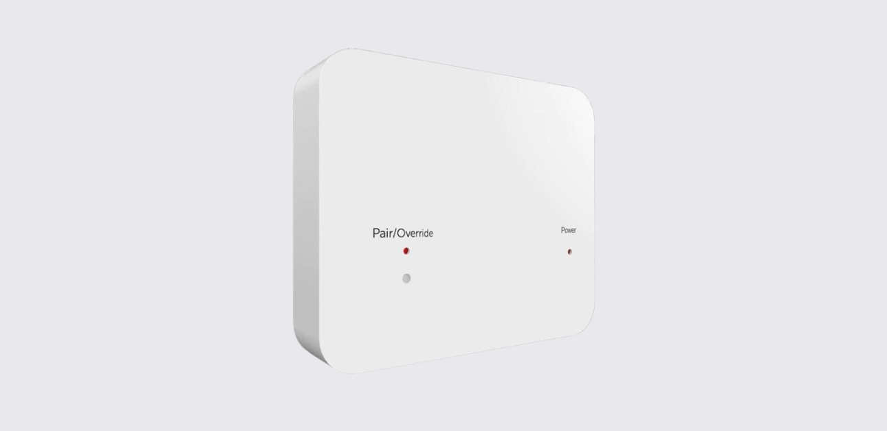
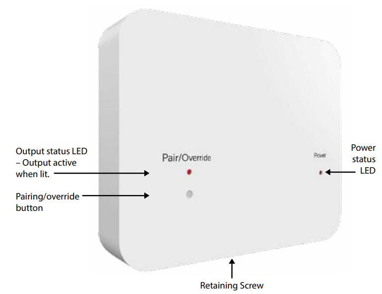
The RF-Switch 16A has a clean front panel with basic controls and indicators.
Main Parts
| Part | Purpose |
| Power status LED | Lights when power is supplied to the receiver |
| Output status LED | Lights when the output is active |
| Pairing/override button | Used for pairing, manual override, and factory reset |
| Retaining screw | Secures the front panel to the back plate |
| Back plate | Mounts to the wall/back box and holds the wiring terminals |
Product Specifications
The manual provides the following key specification details:
| Specification | Detail |
| Product model | Heatmiser RF-Switch 16A |
| Power supply | 230VAC |
| Maximum load | 16 amp load max |
| Wiring terminals | Load, Live, Neutral, Earth |
| Control type | Wireless receiver switch |
| Compatible use | Wireless thermostat-controlled heating receiver |
| Not suitable for | Electric underfloor heating |
How to Install the Heatmiser RF-Switch 16A
The installation process shown in the official manual is straightforward, but it should be performed by a qualified person where required by local electrical rules.
Installation Steps
- Loosen the retaining screw
Use a small screwdriver to slightly loosen the screw at the base of the RF-Switch. - Remove the front panel
Carefully separate the front panel from the back plate. - Mount the back plate
Fix the RF-Switch back plate onto the wall back box using the screws provided. - Connect the wiring
Terminate the cables according to the wiring diagram provided in the manual. - Refit the front panel
Place the front panel back onto the back plate. - Tighten the retaining screw
Secure the front panel by tightening the screw at the base. - Switch on the power supply
Once power is restored, the power LED should illuminate.
Wiring Diagram Summary
The RF-Switch 16A wiring diagram shows connections for:
- 230VAC mains supply
- Live
- Neutral
- Earth
- Load output
- Supply to heater
- Maximum 16 amp load
The diagram on page 2 shows the receiver wired between the mains supply and the connected heating load. The connected load must not exceed 16 amps.
How to Pair the Heatmiser RF-Switch 16A
Pairing allows the receiver to communicate with a compatible Heatmiser wireless thermostat.
Pairing Steps
- Press and hold the pairing button on the RF-Switch for 3 seconds.
- The pairing/override LED will flash.
- Flashing confirms that pairing mode is active.
- Complete the remaining pairing steps from the wireless thermostat.
The manual notes that the exact pairing method depends on the thermostat model, so users should refer to the thermostat’s own instruction manual to complete the process.
How to Manually Override the Output
The RF-Switch 16A includes a manual override function. This lets users switch the receiver output on or off without using the thermostat.
Turn Output On
Press the override button once.
The output will activate, and the output LED will light.
Turn Output Off
Press the override button again.
The output will turn off, and the output LED will go out.
How to Factory Reset the RF-Switch 16A
A factory reset can help when pairing needs to be cleared or the unit needs to be set up again.
Factory Reset Steps
- Press and hold the pairing/override button for 10 seconds.
- During this time, the LED will flash.
- After 10 seconds, the LED will stay permanently solid.
- Release the button.
- The reset procedure is complete.
Troubleshooting Guide
The official manual is short, but the LED behavior and setup steps help identify common issues.
| Problem | Possible Cause | What to Do |
| Power LED does not illuminate | No power supply or wiring issue | Check the 230VAC supply and wiring connections |
| Output LED does not turn on | Output not active | Press the override button once or check thermostat demand |
| Receiver will not pair | Pairing mode not active or thermostat setup incomplete | Hold the pairing button for 3 seconds and follow the thermostat manual |
| Output stays on or off unexpectedly | Manual override may be active | Press the override button again to change output state |
| Pairing needs to be cleared | Previous pairing stored | Perform a factory reset by holding the button for 10 seconds |
| Heating load not switching | Wiring, load, or thermostat issue | Check wiring diagram, load rating, and thermostat pairing |
Contact Support
Heatmiser provides support and technical information for the RF-Switch 16A.
Heatmiser Support
- Support phone: +44 (0)1254 669090
- Website: www.heatmiser.com
- Twitter/X: @heatmiseruk
Facebook: facebook.com/thermostats