| Field | Details |
| Document Title | T10 Pro Smart Thermostat with RedLINK Professional Install Guide |
| Document Type | Professional Installation Guide |
| Brand Name | Honeywell Home |
| Product Name | T10 Pro Smart Thermostat with RedLINK |
| Model Number(s) | THX321WFS2001W; THX321WF2001W |
| PDF File Size | 1.23 MB |
| Total Number of Pages | 48 |
| Languages Covered | English, French, Spanish |
Honeywell Home T10 Pro Smart Thermostat
The Honeywell Home T10 Pro Smart Thermostat with RedLINK is a programmable WiFi thermostat designed to control compatible residential heating, cooling, heat pump, and indoor air quality systems. It combines touchscreen temperature control with wireless room sensors, allowing heating and cooling decisions to be based on temperatures measured in selected rooms.
The T10 Pro operates using a 24 VAC power supply and requires a C-wire connection. It supports conventional single-stage and multistage heating and cooling systems, compatible heat pumps with auxiliary and emergency heating, and selected whole-house humidification, dehumidification, and ventilation equipment.
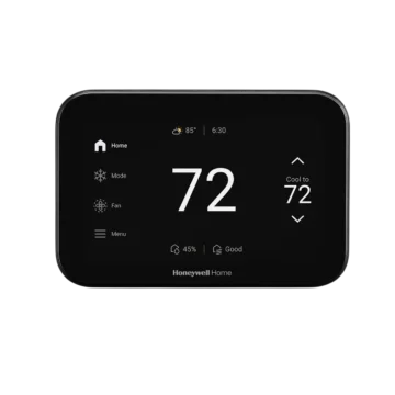
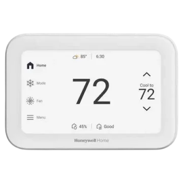
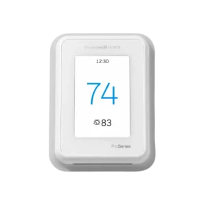
The thermostat includes a touchscreen display showing the current indoor temperature, desired temperature, indoor humidity, and room priority status. Its Menu provides access to system mode, fan operation, scheduling, room priority, wireless sensor management, installer configuration, and equipment testing.
A RedLINK Wireless Indoor Air Sensor is included with the THX321WFS2001W package. The sensor communicates wirelessly with the thermostat and can provide temperature measurements from another room.
The thermostat supports two room priority methods: Selected Rooms and Active Rooms. Selected Rooms calculates an average temperature from manually chosen rooms, while Active Rooms automatically includes rooms where motion is detected.
Additional functions include WiFi setup, installer testing, indoor air quality equipment control, maintenance reminders, temperature adjustment, compressor protection, and system notifications.
Product Overview and Technical Specifications
| Specification | Details |
| Brand | Honeywell Home |
| Manufacturer | Resideo Technologies, Inc. |
| Product Name | T10 Pro Smart Thermostat with RedLINK |
| Model | THX321WFS2001W |
| Illustrated Model | THX321WF2001W |
| Product Type | Programmable WiFi Smart Thermostat |
| Power Supply | 24 VAC |
| C-Wire Requirement | Required |
| Power Consumption | 3 VA |
| Display | Touchscreen |
| WiFi Connectivity | Supported |
| Wireless Room Sensor | RedLINK Wireless Indoor Air Sensor |
| Included Sensor Quantity | 1 |
| Wireless Sensor Batteries | 2 AAA alkaline batteries |
| Conventional HVAC | Single-stage and multistage systems |
| Heat Pump Compatibility | Supported |
| Maximum Conventional Stages Shown | 2 Heat / 2 Cool |
| Maximum Heat Pump Stages Shown | 3 Heat / 2 Cool |
| Wired Sensor Input | S/S terminals |
| Indoor Air Quality Control | Humidification, dehumidification, ventilation |
| Compatible C-Wire Adapter | THP9045A1098 |
| Mounting System | UWP |
| Heating Temperature Range | 40–90°F (4.5–32°C) |
| Cooling Temperature Range | 50–99°F (10–37°C) |
| Operating Temperature | 32–120°F (0–48.9°C) |
| Shipping Temperature | -20–120°F (-28.9–48.9°C) |
| Operating Relative Humidity | 5–90%, non-condensing |
| Installer Setup | Supported |
| Installer Test | Supported |
| Compressor Protection | Supported |
| Limited Warranty | 5 years |
System Compatibility
The Honeywell Home T10 Pro Smart Thermostat is designed for most low-voltage residential heating and cooling systems.
Compatible Heating and Cooling Systems
The installation guide provides wiring arrangements for:
- Conventional 1 Heat / 1 Cool systems with one transformer.
- Conventional 1 Heat / 1 Cool systems with two transformers.
- Conventional 2 Heat / 2 Cool systems.
- Heat-only systems with a fan.
- Cooling-only systems with a fan.
- Hot water relay panels.
- 1 Heat / 1 Cool heat pumps.
- 2 Heat / 1 Cool heat pumps.
- 2 Heat / 2 Cool heat pumps.
- 3 Heat / 2 Cool heat pumps.
Indoor Air Quality Equipment
The U terminals support compatible equipment used for:
- Whole-house humidification.
- Whole-house dehumidification.
- Ventilation.
- Fresh-air damper operation.
- Low-speed fan operation for dehumidification.
The required wiring arrangement depends on how the indoor air quality equipment receives power.
Incompatible Systems
| System | Compatibility |
| Most 24 VAC heating and cooling systems | Compatible |
| Compatible heat pump systems | Compatible |
| 120–240V electric baseboard heating | Not compatible |
| Millivolt heating systems | Not compatible |
Important: The T10 Pro requires 24 VAC power and a C-wire. It must not be connected directly to 120V or 240V electric baseboard heating.
What’s Included in the Box
The THX321WFS2001W package includes the thermostat, mounting components, and one wireless indoor air sensor.
| Included Component | Description |
| T10 Pro Smart Thermostat | Main touchscreen temperature controller |
| UWP Mounting System | Wall-mounted base for wiring and thermostat installation |
| Standard Installation Adapter | Junction box adapter |
| Medium Cover Plate | Covers a junction box or wall paint gap |
| RedLINK Wireless Indoor Air Sensor | Measures temperature in a selected room |
| Screws and Anchors | Secure the mounting system |
| Professional Install Guide | Installation and equipment wiring instructions |
| Getting Started Guide | Initial setup and operating instructions |
Included Medium Cover Plate
The medium cover plate measures:
5-11/64 × 5-1/2 × 11/16 inches (131.4 × 139.7 × 17.5 mm).
Optional Large Cover Plate
The optional large cover plate, model THP2400A1068, measures:
6-7/64 × 6-7/64 × 9/32 inches (155 × 155 × 7 mm).
Parts, Components, and Touchscreen Controls
The thermostat uses a touchscreen interface and a UWP mounting system with electrical terminal connections.
Main Components
| Component | Function |
| Touchscreen Display | Displays temperature, humidity, and operating information |
| Current Indoor Temperature | Shows the measured indoor temperature |
| Desired Temperature | Shows the selected temperature |
| Up Arrow | Increases the selected temperature |
| Down Arrow | Decreases the selected temperature |
| Menu | Opens operating and configuration settings |
| Current Priority | Displays the room priority method and number of prioritized rooms |
| Indoor Humidity | Shows the current indoor humidity |
| UWP Mounting System | Connects the thermostat to the wall and HVAC wiring |
| R Slider Tab | Configures one- or two-transformer systems |
| U Slider Tab | Configures indoor air quality equipment connections |
| S/S Terminals | Accept a compatible wired indoor or outdoor sensor |
| RedLINK Wireless Sensor | Provides temperature measurements from another room |
Understanding the Thermostat Home Screen
The display shows the current indoor temperature and the selected target temperature.
Waking the Screen
Touch the center of the displayed temperature to wake the screen.
Indoor Temperature
The main temperature reading identifies the current indoor temperature.
Desired Temperature
The desired temperature is the heating or cooling target selected for the thermostat.
Adjusting the Temperature
- Wake the touchscreen.
- Touch the Up Arrow to increase the temperature.
- Touch the Down Arrow to decrease the temperature.
- Stop when the required temperature is displayed.
Current Priority
The Current Priority indicator shows which room priority method is active and how many rooms are being prioritized.
Indoor Humidity
The Indoor Humidity area displays the measured indoor humidity level.
Menu
The Menu contains operating features and thermostat configuration options, including:
- Mode.
- Fan.
- Schedule.
- Priority.
- Installer Setup.
- Devices & Sensors.
- Thermostat Information.
Safety Instructions and Important Warnings
The T10 Pro must be installed according to the connected equipment’s electrical requirements.
Electrical Hazard
Warning: Electrical shock or equipment damage can occur if power is not disconnected before installation.
Disconnect the power supply before beginning thermostat installation or handling electrical connections.
Equipment Damage Hazard
Compressor protection is bypassed during installer testing.
Avoid rapidly switching the compressor on and off during testing. Rapid cycling may damage the equipment.
Mercury Disposal Warning
If the thermostat replaces an older control containing mercury in a sealed tube, the old thermostat must not be placed in household trash.
Contact the local waste management authority for recycling and disposal instructions.
Wiring Precautions
- Use 18–22 gauge thermostat wire.
- Shielded cable is not required.
- Connect each wire to the correct UWP terminal.
- Insert only one wire into each terminal.
- Set the R slider according to the transformer arrangement.
- Set the U slider according to the connected indoor air quality equipment.
- Do not connect heat pump auxiliary heating to the W terminal.
- Confirm that a 24 VAC common connection is available.
- Follow the wiring arrangement for the installed HVAC equipment.
Electrical installation and equipment connections should be completed by an appropriately qualified professional.
Installing the UWP Mounting System
The T10 Pro is installed using the included UWP mounting system.
Step 1: Locate the UWP
Remove the UWP mounting system from the package.
Step 2: Position the UWP
- Place the UWP against the wall.
- Use a level to align it.
- Mark the mounting-hole positions.
Step 3: Drill the Mounting Holes
Drill holes at the marked positions.
The drill bit size depends on the supplied wall anchors.
| Anchor Color | Drill Bit Size |
| Red | 7/32 inch (5.6 mm) |
| Yellow | 3/16 inch (4.76 mm) |
Step 4: Install the Wall Anchors
Lightly tap the supplied anchors into the wall using a hammer.
Step 5: Insert the Thermostat Wires
- Open the UWP wiring door.
- Pass the thermostat wires through the wiring opening.
- Arrange the wires so they can reach their assigned terminals.
Step 6: Secure the UWP
- Position the UWP over the wall anchors.
- Insert the mounting screws.
- Tighten until the UWP no longer moves.
- Do not overtighten.
- Close the UWP door after completing the wiring.
Mounting Screw Sizes
| Anchor Type | Screws |
| Red | Three #8 × 1-1/2-inch screws |
| Yellow | Three #6 × 1-1/2-inch screws |
Installing the Optional Cover Plate
The cover plate can be used when the thermostat is mounted to an electrical junction box or when a visible paint gap remains after removing an older thermostat.
Installation Procedure
- Separate the junction box adapter from the cover plate.
- Position the adapter against the wall or electrical box.
- Select suitable mounting positions from the eight available screw holes.
- Insert the two supplied #6 × 5/8-inch screws.
- Tighten the screws without overtightening.
- Confirm that the adapter plate is level.
- Hang the UWP on the upper hook of the junction box adapter.
- Snap the bottom of the UWP into place.
- Attach the cover plate to the junction box adapter.
Understanding the UWP Wiring Terminals
The UWP provides electrical connections for heating, cooling, fan control, temperature sensors, and indoor air quality equipment.
Conventional System Terminal Identification
| Terminal | Function |
| S/S | Wired indoor or outdoor temperature sensor |
| Y | Compressor Stage 1 |
| Y2 | Compressor Stage 2 |
| G | Fan relay |
| C | 24 VAC common |
| K | C-wire adapter connection |
| U/U | Humidifier, dehumidifier, or ventilator relay |
| W | Heating Stage 1 |
| W2 | Heating Stage 2 |
| R | 24 VAC heating transformer |
| Rc | 24 VAC cooling transformer |
Heat Pump Terminal Identification
| Terminal | Function |
| S/S | Wired indoor or outdoor temperature sensor |
| Y | Compressor Stage 1 |
| Y2 | Compressor Stage 2 |
| G | Fan relay |
| C | 24 VAC common |
| K | C-wire adapter connection |
| U/U | Humidifier, dehumidifier, or ventilator relay |
| L/A | Compressor monitoring or heat pump fault input |
| O/B | Heat pump changeover valve |
| Aux | Backup heating |
| E | Emergency heating |
| R | 24 VAC heating transformer |
| Rc | 24 VAC cooling transformer |
Connecting Wires to the UWP
- Locate the required terminal.
- Push down its terminal tab.
- Insert the wire into the inner terminal hole.
- Release the tab.
- Gently pull the wire to confirm that it is secure.
Only one wire should be inserted into each terminal.
Removing a Wire
Press the corresponding terminal tab and withdraw the wire.
Setting the R Slider Tab
The R slider determines whether the installation uses one transformer or separate heating and cooling transformers.
One-Transformer System
If the existing thermostat has one wire connected to R, Rc, or RH:
- Locate the R slider.
- Move it to the UP position.
- Use the one-wire R configuration.
Two-Transformer System
If separate wires are connected to R and Rc:
- Locate the R slider.
- Move it to the DOWN position.
- Use the two-wire configuration.
R Slider Position Table
| Existing Wiring | Slider Position |
| One R, Rc, or RH wire | UP |
| Separate R and Rc wires | DOWN |
The built-in R slider performs the jumper function required for the selected transformer arrangement.
Setting the U Slider Tab
The U slider controls how compatible indoor air quality equipment is connected.
U Slider DOWN: Two-Wire Dry Contacts
When the U slider is DOWN, the U terminals provide dry contacts.
This arrangement is used for equipment with its own transformer.
U Slider UP: One-Wire Connection
When the U slider is UP, the lower U terminal is internally connected to Rc.
This arrangement is used when the indoor air quality device is powered by the cooling transformer.
How the One-Wire Connection Works
- Move the U slider to UP.
- Connect one wire from the indoor air quality device to the upper U terminal.
- Connect the other device wire to the common side of the cooling transformer.
U Slider Reference Table
| Slider Position | Connection Type | Application |
| DOWN | Two-wire dry contacts | Equipment with its own power supply |
| UP | One-wire arrangement | Equipment powered by cooling transformer |
The one-wire arrangement is commonly used for a fresh-air ventilation damper or low-speed fan dehumidification.
Connecting Indoor Air Quality Equipment
The T10 Pro supports several indoor air quality wiring arrangements through its U terminals.
Humidifier, Dehumidifier, or Ventilator With Built-In Transformer
When the connected equipment has its own transformer, the U slider is set to the dry-contact arrangement.
Fresh-Air Damper Powered by Furnace Transformer
A compatible fresh-air damper can use the one-wire arrangement.
The damper connection uses the furnace or air handler’s common terminal.
Equipment Powered by an External Transformer
An externally powered humidifier, ventilator, or damper uses the dry-contact arrangement.
Low-Speed Fan for Dehumidification
The one-wire arrangement can also control a compatible low-speed fan terminal used for dehumidification.
Terminal names on the connected equipment may vary.
Using the THP9045A1098 C-Wire Adapter
The thermostat requires a C-wire.
The optional THP9045A1098 C-Wire Adapter can be used on compatible heating and cooling systems when only four thermostat wires are available and a fifth wire is needed for common power.
How the Adapter Works
The adapter uses the K terminal in place of separate Y and G connections.
This allows fan and compressor control through one wire.
The unused conductor can then provide the required common connection.
C-Wire Adapter Connections
| Connection | Function |
| K | Combined fan and compressor control through adapter |
| C | 24 VAC common |
| THP9045A1098 | Compatible C-wire adapter |
The adapter must be installed according to its own THP9045 instructions.
Conventional Heating and Cooling Wiring
The thermostat supports several conventional HVAC wiring configurations.
1 Heat / 1 Cool System With One Transformer
| Terminal | Connection |
| R | Power |
| Rc | Joined to R through slider |
| Y | Compressor contactor |
| C | 24 VAC common |
| W | Heat relay |
| G | Fan relay |
The R slider is placed in the UP position.
1 Heat / 1 Cool System With Two Transformers
| Terminal | Connection |
| R | Heating transformer power |
| Rc | Cooling transformer power |
| Y | Compressor contactor |
| C | Common from cooling transformer |
| W | Heat relay |
| G | Fan relay |
The R slider is placed in the DOWN position.
2 Heat / 2 Cool System With One Transformer
| Terminal | Connection |
| R | Power |
| Rc | Joined to R through slider |
| Y | Compressor Stage 1 |
| Y2 | Compressor Stage 2 |
| C | 24 VAC common |
| W | Heating Stage 1 |
| W2 | Heating Stage 2 |
| G | Fan relay |
Heat-Only System With Fan
| Terminal | Connection |
| R | Power |
| Rc | Joined through slider |
| C | 24 VAC common |
| W | Heating relay |
| G | Fan relay |
Cool-Only System With Fan
| Terminal | Connection |
| R | Power |
| Rc | Joined through slider |
| Y | Compressor contactor |
| C | 24 VAC common |
| G | Fan relay |
Hot Water Relay Panel
| Terminal | Connection |
| R | Power |
| Rc | Joined through slider |
| W | Heat relay |
| C | 24 VAC common |
If the hot water relay panel does not provide 24 VAC at R and C, the manufacturer directs the installer to move the slider DOWN and connect a separate transformer to Rc and C.
Heat Pump Wiring
The T10 Pro supports heat pumps with different compressor and auxiliary heating arrangements.
Important: The W terminal must not be used for heat pump applications. Auxiliary heating must be connected to AUX or E.
1 Heat / 1 Cool Heat Pump
| Terminal | Connection |
| R | Power |
| Rc | Joined through slider |
| Y | Compressor contactor |
| C | 24 VAC common |
| O/B | Changeover valve |
| G | Fan relay |
2 Heat / 1 Cool Heat Pump
| Terminal | Connection |
| R | Power |
| Rc | Joined through slider |
| Y | Compressor contactor |
| C | 24 VAC common |
| O/B | Changeover valve |
| G | Fan relay |
| Aux | Auxiliary heating |
| E | Emergency heating relay |
| L | Heat pump fault input |
2 Heat / 2 Cool Heat Pump
| Terminal | Connection |
| R | Power |
| Rc | Joined through slider |
| Y | Compressor Stage 1 |
| Y2 | Compressor Stage 2 |
| C | 24 VAC common |
| O/B | Changeover valve |
| G | Fan relay |
| L | Heat pump fault input |
3 Heat / 2 Cool Heat Pump
| Terminal | Connection |
| R | Power |
| Rc | Joined through slider |
| Y | Compressor Stage 1 |
| Y2 | Compressor Stage 2 |
| C | 24 VAC common |
| O/B | Changeover valve |
| G | Fan relay |
| Aux | Auxiliary heating |
| E | Emergency heating relay |
| L | Heat pump fault input |
Auxiliary and Emergency Heat Wiring
If separate wires are available for Aux and E, connect them to their respective terminals.
If only one wire is available for both auxiliary and emergency heat, connect that wire to Aux.
Mounting the Thermostat
After the UWP wiring has been completed, the thermostat can be attached.
Installation Procedure
- Push excess wiring back into the wall opening.
- Close the UWP door.
- Confirm that the door remains closed without bulging.
- Align the thermostat with the UWP.
- Press gently until the thermostat snaps into place.
Installation With the Optional Cover Plate
If the optional cover plate is used, remove the gray trim ring from the thermostat before attaching it.
Align the thermostat with the cover plate and press until it snaps into place.
Removing the Thermostat
The thermostat can be removed from the UWP by pulling it gently away from the mounting system.
Initial Installer Setup
After installation, the thermostat displays a guided setup process.
The setup covers equipment configuration, wireless sensor connections, and WiFi setup.
Equipment Configuration
The installer setup process guides the selection of settings required for the connected heating and cooling equipment.
Wireless Sensor Connection
Compatible RedLINK wireless sensors can be added during setup.
WiFi Connection
The thermostat provides on-screen instructions for connecting to WiFi.
Installer Contact Information
The final setup stage allows the installer to enter:
- Company name.
- Contact information.
- Contractor PRO account number.
Stored installer contact information can appear with alert or reminder messages.
Contractor PRO Account Number
The Contractor PRO account number contains eight digits and begins with zero.
For example:
01234567
Installing the RedLINK Wireless Indoor Air Sensor
One RedLINK Wireless Indoor Air Sensor is supplied with the specified package.
The sensor uses two AAA alkaline batteries.
Step 1: Open the Sensor
Remove the white cover from the gray sensor base.
Step 2: Install the Batteries
Insert two AAA alkaline batteries into the sensor.
Step 3: Open the Thermostat Menu
Wake the thermostat and open Menu.
Step 4: Select Devices & Sensors
Touch Devices & Sensors.
Step 5: Add the Sensor
- Touch Add.
- Follow the instructions on the thermostat display.
Step 6: Assemble the Sensor
Snap the sensor onto its wall plate.
Step 7: Mount the Sensor
- Attach the included adhesive strip to the sensor wall plate.
- Position the sensor at the selected location.
- Attach the wall plate to the wall.
- Level the sensor for a neat appearance.
The sensor’s own instructions provide its placement requirements.
Understanding RedLINK Room Priority
The T10 Pro can use temperature measurements from selected rooms to calculate an average indoor temperature.
This allows temperature control to be based on different areas of the home.
Selected Rooms
Selected Rooms uses sensors chosen manually.
| Room Status | Temperature Averaging |
| Selected | Included |
| Not Selected | Excluded |
Active Rooms
Active Rooms uses detected motion to decide which rooms contribute to the average temperature.
| Room Status | Temperature Averaging |
| Motion Detected | Included |
| No Motion Detected | Excluded |
Example of Selected Rooms
If the living room and bedroom are selected, their temperature measurements contribute to the average.
Unselected rooms do not contribute.
Example of Active Rooms
If motion is detected in the living room, its temperature contributes to the average.
A room without detected activity does not contribute.
Thermostat Menu Options
The T10 Pro Menu contains operating functions and installer configuration settings.
How to Open Menu
- Wake the touchscreen.
- Touch Menu.
- Scroll upward or downward to view the available options.
Main Menu Functions
| Menu | Function |
| Installer Setup | Configures HVAC system and indoor air quality settings |
| Installer Test | Tests heating, cooling, and indoor air quality equipment |
| Devices & Sensors | Manages RedLINK wireless sensors |
| Thermostat Information | Displays identification and software details |
| Dealer Information | Shows installer or dealer contact information |
Installer Setup
The Installer Setup menu contains options related to:
- Heating and cooling system type.
- Humidification.
- Dehumidification.
- Ventilation.
- Maintenance reminders.
Installer Test
Installer Test can activate:
- Heating equipment.
- Cooling equipment.
- Indoor air quality equipment.
Compressor protection is bypassed during testing. Avoid rapid compressor cycling.
Devices & Sensors
This menu allows compatible RedLINK indoor sensors to be viewed, added, removed, or identified.
Thermostat Information
The Thermostat Information menu displays device identification and software information.
Available Information
| Field | Description |
| MAC ID | Network hardware identifier |
| IP Address | Assigned network address |
| Date Code | Thermostat date code |
| Model Number | Product model identification |
| Build Date | Device or software build information |
| Stat App | Thermostat application information |
| Firmware Version | Installed firmware version |
| Stat App Boot Number | Application boot information |
| Hardware | Hardware identification |
Finding the Installer Setup Passcode
The thermostat’s Date Code is used as the installer setup passcode.
- Open Menu.
- Select Thermostat Information.
- Locate the Date Code.
- Record the code for installer setup access.
Alerts and Notifications
The T10 Pro provides notifications when attention is required.
Red Notification Indicator
A red dot above the Menu icon indicates that an alert or notification is active.
How to View Alerts
- Touch Menu.
- Select Notifications.
- Choose the required alert message.
- Read the additional information displayed.
Example Notification
The thermostat may display a notification requesting that the date and time be set.
The Notifications menu provides details about the active message.
Troubleshooting the T10 Pro Smart Thermostat
Thermostat Screen Is Blank
If the display is blank:
- Check the circuit breaker.
- Reset the breaker if necessary.
- Confirm that the heating and cooling equipment power switch is on.
- Make sure the furnace door is closed securely.
Screen Is Difficult to Read
The inactive backlight settings may require adjustment.
Open:
Menu > Preferences
Check:
- Inactive Backlight Brightness.
- Inactive Sleep Backlight Brightness.
Adjust the relevant setting to improve screen visibility.
Heating System Does Not Respond
- Open Menu.
- Select the system mode.
- Choose Heat.
- Set the heating temperature above the current indoor temperature.
- Check the circuit breaker.
- Confirm that the heating equipment power switch is on.
- Check that the furnace door is closed securely.
Cooling System Does Not Respond
- Open Menu.
- Select the system mode.
- Choose Cool.
- Set the cooling temperature below the current indoor temperature.
- Check the circuit breaker.
- Confirm that the cooling equipment power switch is on.
- Check that the furnace door is closed securely.
Temperature Settings Cannot Be Changed
Confirm that the selected temperature is within the supported range.
| Mode | Allowed Range |
| Heating | 40–90°F (4.5–32°C) |
| Cooling | 50–99°F (10–37°C) |
Heat On or Cool On Is Flashing
A flashing Heat On or Cool On message indicates that compressor protection is active.
Wait approximately five minutes for the system to restart safely.
Auxiliary Heat Operates During Cooling
For a heat pump system, check that no wire is connected to W on the UWP.
Cooling Operates When Heating Is Requested
For a heat pump system, verify that W is not being used.
Heating Operates During Cooling
Check the heat pump wiring.
The W terminal must not be connected for heat pump applications.
Wireless Sensor Does Not Connect
- Press and hold Connect on the wireless sensor for 15 seconds.
- Wait until the LED turns amber.
- Return to the thermostat.
- Open Menu.
- Select Devices & Sensors.
- Follow the instructions to add the sensor again.
Troubleshooting Reference Table
| Problem | Check or Cause | Recommended Action |
| Blank display | Circuit breaker or equipment power | Check power supply |
| Blank display | Furnace door | Close furnace door securely |
| Screen difficult to read | Backlight brightness | Adjust Preferences |
| Heating does not start | System mode or setpoint | Select Heat and increase target |
| Cooling does not start | System mode or setpoint | Select Cool and decrease target |
| Cannot change temperature | Temperature outside supported range | Check setpoint range |
| Heat On flashes | Compressor protection | Wait five minutes |
| Cool On flashes | Compressor protection | Wait five minutes |
| Auxiliary heat runs in cooling | Heat pump wiring | Verify W is unused |
| Cooling runs with heating demand | Heat pump wiring | Check W terminal |
| Heating runs during cooling | Heat pump wiring | Check W terminal |
| Wireless sensor will not pair | Sensor connection | Hold Connect for 15 seconds and pair again |
Physical Dimensions
The thermostat and mounting accessories have the following dimensions.
| Component | Dimensions |
| T10 Pro Thermostat | 4.9 × 3.7 × 0.93 inches (125.4 × 94.1 × 23.68 mm) |
| UWP Mounting System | 58 × 56 × 10 mm |
| Standard Installation Adapter | 3-29/32 × 3-57/64 × 21/32 inches (99 × 99 × 17 mm) |
| Medium Cover Plate | 5-11/64 × 5-1/2 × 11/16 inches (131.4 × 139.7 × 17.5 mm) |
| Large Cover Plate THP2400A1068 | 6-7/64 × 6-7/64 × 9/32 inches (155 × 155 × 7 mm) |
Operating and Environmental Specifications
| Specification | Value |
| Heating Temperature Range | 40–90°F (4.5–32°C) |
| Cooling Temperature Range | 50–99°F (10–37°C) |
| Operating Ambient Temperature | 32–120°F (0–48.9°C) |
| Shipping Temperature | -20–120°F (-28.9–48.9°C) |
| Operating Relative Humidity | 5–90%, non-condensing |
| Power Consumption | 3 VA |
Electrical Ratings
The terminal ratings are specified for 50/60 Hz operation.
| Terminal | Voltage | Running Current |
| W Heating | 20–30 VAC | 0.02–1.0 A |
| W2 Auxiliary Heating | 20–30 VAC | 0.02–1.0 A |
| E Emergency Heat | 20–30 VAC | 0.02–0.5 A |
| Y Compressor Stage 1 | 20–30 VAC | 0.02–1.0 A |
| Y2 Compressor Stage 2 | 20–30 VAC | 0.02–1.0 A |
| G Fan | 20–30 VAC | 0.02–0.5 A |
| O/B Changeover | 20–30 VAC | 0.02–0.5 A |
| L/A Input | 20–30 VAC | 0.02–0.5 A |
| U | 20–30 VAC | 0.02–0.5 A |
The electrical ratings table also identifies a Powerpile value of 750 mV DC at 100 mA DC. However, the manufacturer’s compatibility instructions specifically state that this thermostat does not work with millivolt heating systems. The Powerpile entry must not be interpreted as approval for a millivolt installation.
Replacement Parts and Accessories
The following accessories are identified in the installation instructions.
| Accessory | Model or Specification | Purpose |
| C-Wire Adapter | THP9045A1098 | Provides a common-wire arrangement for compatible four-wire installations |
| Large Cover Plate | THP2400A1068 | Covers larger wall openings or paint gaps |
| RedLINK Wireless Indoor Air Sensor | Compatible RedLINK indoor sensor | Provides wireless room temperature information |
| Sensor Batteries | 2 AAA alkaline batteries | Power the wireless sensor |
| UWP Mounting System | UWP | Provides wiring and wall mounting |
| Medium Cover Plate | 131.4 × 139.7 × 17.5 mm | Covers wall gaps or junction box installation |
Regulatory Information
FCC Compliance
The thermostat complies with Part 15 of the FCC Rules.
Operation is subject to the following conditions:
- The device must not cause harmful interference.
- The device must accept received interference, including interference that may cause undesired operation.
FCC Modification Warning
Changes or modifications not approved by the responsible party may void authorization to operate the equipment.
Canadian Regulatory Compliance
The thermostat complies with applicable Industry Canada licence-exempt radio equipment requirements.
It must not cause interference and must accept received interference, including interference that may affect normal operation.
Electronic Waste Disposal
The thermostat must not be discarded with ordinary household waste at the end of its service life.
Use an authorized electronic waste collection center or approved recycler.
Correct disposal helps reduce potential environmental and human health effects.
Warranty Information
The Honeywell Home T10 Pro Smart Thermostat includes a 5-year limited warranty.
| Warranty Information | Details |
| Warranty Type | Limited Warranty |
| Warranty Period | 5 Years |
| Manufacturer | Resideo Technologies, Inc. |
| Warranty Website | https://www.honeywellhome.com |
Customer Support and Manufacturer Information
The T10 Pro Smart Thermostat is manufactured by Resideo Technologies, Inc. under license to use the Honeywell Home trademark.
| Information | Details |
| Brand | Honeywell Home |
| Manufacturer | Resideo Technologies, Inc. |
| Product | T10 Pro Smart Thermostat with RedLINK |
| Model | THX321WFS2001W |
| Customer Support | 1-800-633-3991 |
| Official Website | https://www.honeywellhome.com |
| Manufacturer Website | https://www.resideo.com |
| Manufacturer Address | 1985 Douglas Drive North, Golden Valley, MN 55422, USA |
| Contractor PRO Support | 1-800-919-4835 |
| Contractor PRO Email | contractorpro@resideo.com |
| Utility Rebates | https://www.honeywellhome.com/Rebates |
Frequently Asked Questions
1. Does the Honeywell Home T10 Pro THX321WFS2001W require a C-wire?
Yes. The T10 Pro requires 24 VAC power through a C-wire connection.
If a C-wire is unavailable, the optional THP9045A1098 C-Wire Adapter can be used in compatible installations.
The adapter uses the K terminal to combine fan and compressor control, allowing an unused conductor to provide the required common connection.
2. How is the Honeywell T10 Pro Smart Thermostat installed?
The thermostat uses the included UWP mounting system.
The UWP is secured to the wall, and the heating and cooling equipment wires are connected to the appropriate terminals.
The R and U slider positions must match the installed equipment.
After completing the wiring, the UWP door is closed and the thermostat is snapped into place.
The touchscreen then guides the installer through system configuration, wireless sensor pairing, and WiFi setup.
3. How is a RedLINK Wireless Indoor Air Sensor paired with the T10 Pro?
Remove the sensor cover and install two AAA alkaline batteries.
On the thermostat, open Menu, select Devices & Sensors, and touch Add.
Follow the on-screen instructions to complete pairing.
The sensor can then be attached to its wall plate and mounted with the supplied adhesive strip.
4. How does room priority work on the T10 Pro?
Room Priority allows the thermostat to calculate an average temperature using selected rooms.
Selected Rooms includes measurements from manually chosen rooms.
Active Rooms automatically includes rooms where motion is detected.
Rooms that are not selected or do not detect activity are excluded according to the selected priority mode.
5. Why is Heat On or Cool On flashing on the thermostat?
A flashing Heat On or Cool On message indicates that compressor protection is active.
The thermostat temporarily delays the heating or cooling equipment to prevent rapid compressor cycling.
Wait approximately five minutes for the equipment to restart safely.
6. Why is the T10 Pro thermostat screen blank?
Check the circuit breaker and reset it if necessary.
Confirm that the heating and cooling equipment power switch is on.
Also make sure the furnace door is securely closed.
These are the primary checks identified for a blank thermostat display.
7. How is a RedLINK sensor reconnected when pairing fails?
Press and hold the sensor’s Connect button for 15 seconds until the LED turns amber.
Return to the thermostat and open Menu > Devices & Sensors.
Follow the on-screen instructions to add the sensor again.
8. What warranty comes with the Honeywell Home T10 Pro Smart Thermostat?
The T10 Pro includes a five-year limited warranty.
Warranty information is available from Honeywell Home at https://www.honeywellhome.com.