
The Heatmiser TM4 V2 is a 4-channel time clock designed to control up to four timed outputs or zones. It belongs to the Heatmiser Time Clock Series and allows users to program different switching times for each zone.
The official user manual covers installation, LCD display icons, normal run mode, clock setup, holiday mode, 5/2 day and 7 day programming, switching times, copy function, boost facility, mode selection, wiring diagram, and Heatmiser support details.
Key Features
The Heatmiser TM4 V2 is built for multi-zone timed control. Its main features include:
- 4 independent time clock zones
- Flush-mounted wall installation
- 5/2 day programming
- 7 day programming
- Four switching times per zone
- Zone status display
- Holiday mode
- Copy function between zones
- Boost facility
- Auto, Constant, and Off modes
- 230VAC wiring
- Switched live outputs for CH1 to CH4
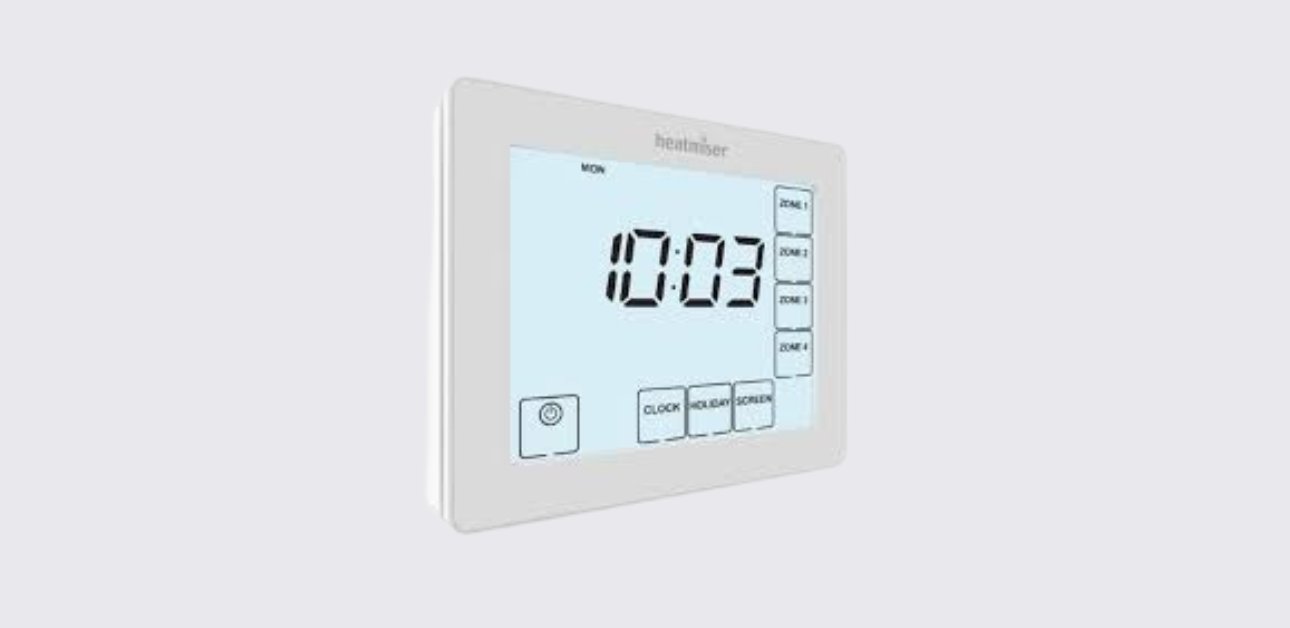
Parts and Controls
The TM4 V2 has a large LCD display with touch-style controls for zones and programming.
Main Controls
| Control | Function |
| Power / Cancel | Cancels or exits certain operations |
| Edit | Opens switching time programming |
| Clock / Day | Sets clock and changes day selection |
| Holiday / Boost | Sets holiday duration or timed boost |
| Screen / Mode | Changes display screen or zone mode |
| Done | Confirms settings and exits |
| Zone 1–Zone 4 | Selects the zone to view or program |
| Left Up/Down keys | Adjust values on the left digit group |
| Right Up/Down keys | Adjust values on the right digit group |
LCD Display Icons and Indicators
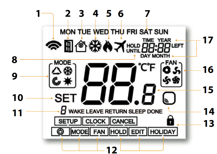
The LCD display shows time, zone status, programming mode, and setup prompts.
| Display Item | Meaning |
| Day indicator | Shows the current day |
| Copy | Shows when the copy function is being used |
| Timer status | Displays current timed output status |
| Left Up/Down keys | Adjust hours or left-side values |
| Right Up/Down keys | Adjust minutes or right-side values |
| Select Zone | Prompts the user to choose a zone |
| Boost Left / Holiday Left | Shows remaining boost time or holiday days |
| Setup/programming keys | Used to move through clock, edit, holiday, boost, mode, and done options |
| Mode status | Shows Auto, Constant, or Off |
| Zone 1–4 display | Shows the selected zone or zone timing screen |
Product Specifications
| Specification | Detail |
| Product model | Heatmiser TM4 V2 |
| Product type | 4-channel time clock |
| Series | Time Clock Series |
| Mounting type | Flush mounted |
| Back box depth | 35mm minimum |
| Power supply | 230VAC |
| Number of zones | 4 zones |
| Outputs | CH1, CH2, CH3, CH4 switched live outputs |
| Programming modes | 5/2 day or 7 day |
| Zone modes | Auto, Constant, Off |
| Holiday mode | Disables all four outputs |
| Boost mode | Turns selected zone on for selected hours |
| Wiring terminals | N, L, CH4, CH3, CH2, CH1 |
How to Install the Heatmiser TM4 V2
The TM4 V2 is designed for flush mounting and requires a 35mm minimum depth back box in the wall before installation.
Installation Steps
- Loosen the retaining screw
Use a small screwdriver to slightly loosen the screw from the bottom face of the time clock. - Separate the front from the back plate
Carefully remove the front half from the back plate. - Place the front safely aside
Keep the display section safe while mounting and wiring. - Wire the time clock
Terminate the wiring according to the wiring diagram shown in the manual. - Secure the back plate
Screw the back plate firmly into the wall back box. - Refit the front panel
Locate the pins in the socket, insert the top edge first, then push in the bottom edge. - Tighten the retaining screw
Secure the front panel in place.
Installation Do’s and Don’ts
| Do | Don’t |
| Mount the time clock at eye level | Do not install near a direct heat source |
| Read the full instructions before use | Do not press hard on the LCD screen |
| Use the wiring diagram before connecting terminals | Do not force the front panel onto the back plate |
Normal Run Mode
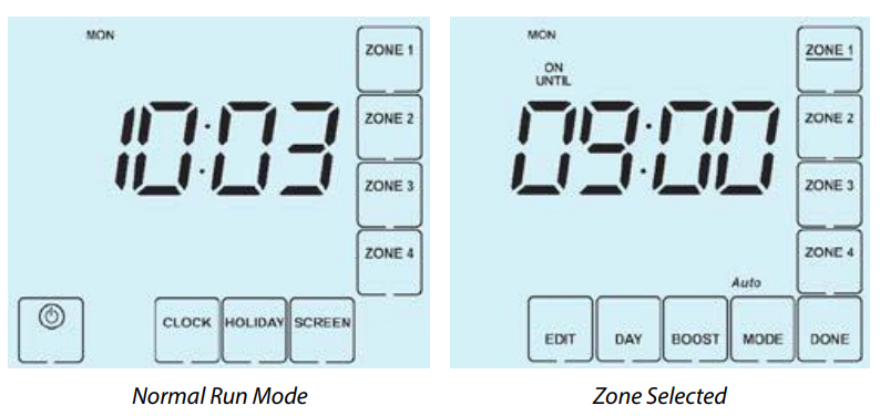
In normal run mode, the TM4 V2 displays the current time.
Users can also view the status of a specific zone by pressing Zone 1, Zone 2, Zone 3, or Zone 4. The selected zone screen remains visible until DONE is pressed to return to the main menu.
Setting the Clock
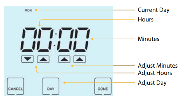
To set the clock:
- Press the Clock key.
- Use the Left Up/Down keys to set the hour.
- Use the Right Up/Down keys to set the minute.
- Press the Day key to set the day.
- Press DONE to confirm and exit.
The display shows the current day, hours, and minutes while the clock is being adjusted.
Holiday Mode
Holiday mode disables all four timed outputs for the selected number of days. At the end of the holiday period, the TM4 V2 returns to the programmed schedule.
How Holiday Mode Works
- All four outputs are disabled during the holiday period.
- The holiday period starts at 00:00 the next day.
- The time clock returns to its programmed schedule when the holiday ends.
Example: if a 2-day holiday is set on Friday, Saturday is counted as day one, and the time clock returns to the programmed schedule at 00:00 on Monday.
How to Set Holiday Mode
- Press HOLIDAY.
- Enter the required number of holiday days.
- Press DONE to confirm and exit.
To cancel holiday mode, reduce the holiday time to 00 days.
Selecting 5/2 Day or 7 Day Programming
Each zone can be programmed independently in either 5/2 day mode or 7 day mode.
| Programming Mode | Meaning |
| 5/2 Day Mode | Weekdays and weekends can have separate switching times |
| 7 Day Mode | Each day can be programmed separately |
How to Select Programming Mode
- Press the zone you want to program, such as Zone 1.
- Press Day.
- Use the Up/Down arrow keys to choose the programming mode.
- Select:
- 00 = 5/2 Day mode
- 01 = 7 Day mode
- Press DONE to confirm and exit.
In 5/2 day mode, the display shows Mon–Fri for weekday programming. In 7 day mode, the display shows Mon for individual day programming.
Adjusting the Switching Times
Each zone can have multiple switching times. These determine when the selected output turns on or off.
How to Program Switching Times
- Select the zone you want to program, such as Zone 1.
- Press EDIT.
- If the zone is in 5/2 day mode, the display shows Mon, Tue, Wed, Thu, Fri.
- If the zone is in 7 day mode, the display shows Mon.
- Press Day to select the day or day group.
- Use the Up/Down keys to set the ON time.
- Set the OFF time.
- Repeat for Time 2, Time 3, and Time 4.
- Press DONE to confirm and exit.
Copy Function
The TM4 V2 includes a copy function that allows users to copy switching times from one zone to another. This saves time when multiple zones need the same schedule.
How to Use the Copy Function
- Select the zone you want to copy from.
- Press EDIT.
- Press the COPY key.
- Select each zone you want to copy the schedule to.
- Press DONE to confirm and exit.
Mode Select
Each zone can operate in three modes:
| Mode | Function |
| Auto | Zone follows the programmed switching times |
| Constant | Zone remains continuously on |
| Off | Zone remains off |
How to Set Zone Mode
- Select the zone you want to adjust.
- Press Mode until the desired mode appears.
- Press DONE to return to the main screen if needed.
Boost Facility
Each zone has a boost function that turns the selected zone on for a set number of hours. This is useful when extra run time is needed without changing the main schedule.
How to Use Boost
- Select the required zone.
- Press Boost.
- Use the Up/Down arrow keys to enter the boost period in hours.
- Press DONE to confirm.
The remaining boost time appears on screen.
Cancel Boost Early
Repeat the boost steps and reduce the boost time to 00.
Wiring Diagram
The manual includes a wiring diagram for the TM4 V2.
Wiring Terminals
| Terminal | Function |
| N | Neutral |
| L | Live |
| CH1 | Switched live output for Channel 1 |
| CH2 | Switched live output for Channel 2 |
| CH3 | Switched live output for Channel 3 |
| CH4 | Switched live output for Channel 4 |
The wiring diagram shows a 230VAC supply with separate switched live outputs for CH1, CH2, CH3, and CH4.
Troubleshooting Guide
| Problem | Possible Cause | What to Do |
| Display does not turn on | No power supply or wiring issue | Check 230VAC supply and wiring |
| Zone does not switch on | Zone may be in Off mode | Select the zone and change mode to Auto or Constant |
| Zone runs at wrong time | Incorrect switching times | Reprogram the selected zone |
| All outputs are off | Holiday mode may be active | Cancel holiday by setting holiday days to 00 |
| Boost does not work | Wrong zone selected or boost set to 00 | Select correct zone and set boost hours |
| Zone does not follow schedule | Zone may be in Constant or Off mode | Set zone mode to Auto |
| Same schedule needed for multiple zones | Manual setup takes too long | Use the Copy function |
| Time or day is wrong | Clock has not been set correctly | Reset the clock and day |
Support and Contact
Heatmiser provides technical support, PDFs, FAQs, videos, and product specifications through its official support channels.
Heatmiser UK Ltd
Support phone: +44 (0)1254 669090
Website: www.heatmiser.com
Twitter/X: @heatmiseruk
Facebook: facebook.com/thermostatsAddress:
Heatmiser UK Ltd
Units 1-5 Hurstwood Court, Mercer Way
Shadsworth Business Park, Blackburn
Lancashire, BB1 2QU
United Kingdom