
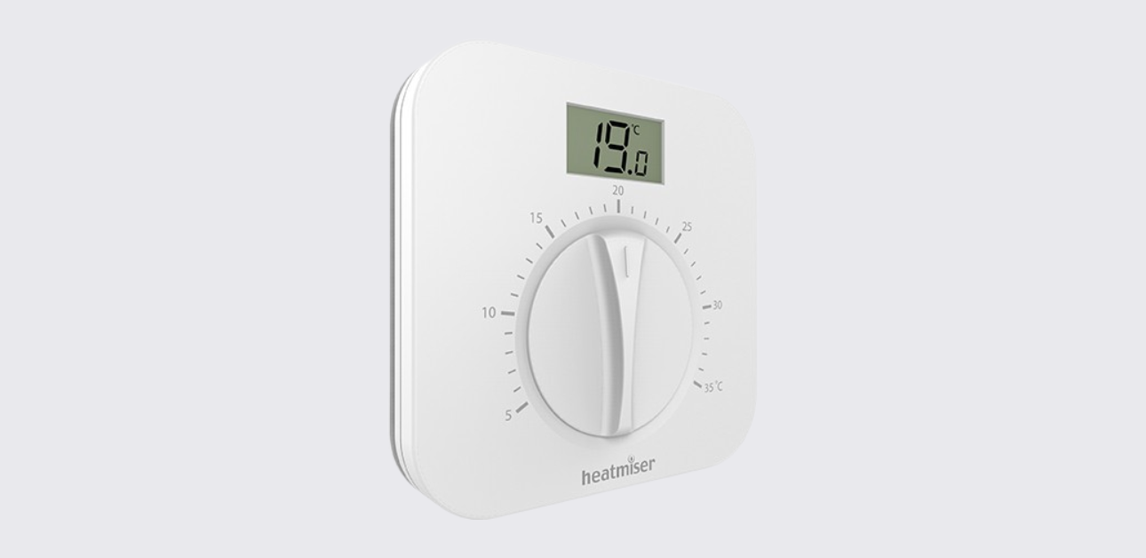
The Heatmiser DS1-L V2 is a manual dial thermostat designed for conventional boiler and combi boiler systems. It combines a simple rotary temperature dial with a small digital LCD display, making it easy to adjust room temperature while still viewing the current ambient temperature.
The official manual covers installation, 230V and volt-free wiring diagrams, temperature setting, switching differential adjustment, display icons, remote sensor use, and Heatmiser support information.
Key Features
The Heatmiser DS1-L V2 includes:
- Manual dial temperature control
- Digital LCD display
- Suitable for conventional and combi boiler systems
- 230V AC power input
- 230V AC, 3A maximum switching output
- Volt-free switching option
- Adjustable switching differential: 1°C, 2°C, or 3°C
- Heating ON display icon
- Optional remote temperature sensor support
- Flush-mounted installation
- IP20 rating
Important Safety Information
Before installation, the manual clearly warns users to turn off power to the heating system to avoid the risk of electric shock. Electrical installation should follow the wiring diagram and local installation requirements.
Parts and Controls
The DS1-L V2 has a simple front layout designed for easy everyday use.
| Part | Function |
| Rotary dial | Sets the desired room temperature |
| LCD display | Shows the ambient room temperature |
| Heating ON icon | Shows when the thermostat enables the boiler |
| Back plate | Mounts into the wall back box |
| DIP switches | Used to set the switching differential |
| Remote sensor terminals | Allow connection of a compatible remote temperature sensor |
Product Specifications
| Specification | Detail |
| Product model | Heatmiser DS1-L V2 |
| Product type | Manual dial thermostat |
| Suitable systems | Conventional or combi boiler systems |
| Input | 230VAC, 50/60Hz |
| Output | 230VAC, 3A max |
| Switching type | 230V switching and volt-free switching |
| IP rating | IP20 |
| Switching differential | 1°C, 2°C, or 3°C |
| Temperature control | Manual rotary dial |
| Display | Digital LCD |
| Remote sensor support | Yes, compatible Heatmiser thimble sensor, not included |
| Mounting type | Flush mounted |
How to Install the Heatmiser DS1-L V2
The DS1-L V2 is designed to be flush mounted.
Installation Steps
- Turn off power
Switch off the power to the heating system before starting installation. - Remove the thermostat front
Unscrew the securing screws on the bottom face of the thermostat and separate the front section from the back plate. - Connect the wiring
Terminate the thermostat according to the correct wiring diagram. - Secure the back plate
Screw the thermostat back plate securely into the wall back box. - Refit the front panel
Clip the thermostat front onto the back plate. - Tighten the retaining screw
Secure the front panel in place with the retaining screw.
Temperature Control Instructions
The DS1-L V2 uses a manual dial rather than touch buttons or app controls.
How to Set the Temperature
To change the temperature set point:
- Rotate the dial.
- Point the dial to the desired temperature.
- The LCD display continues to show the ambient room temperature.
The thermostat will switch the boiler on or off based on the selected set temperature and the configured switching differential.
Heating ON Display Icon
The LCD includes a Heating ON icon. This icon appears when the thermostat enables the boiler.
If the icon is not shown, the thermostat is not currently calling for heat.
Switching Differential
The Heatmiser DS1-L offers 1°C, 2°C, and 3°C switching differential settings.
What Switching Differential Means
| Setting | How It Works |
| 1°C differential | Heating switches on 1°C below the set temperature and turns off when the set temperature is reached |
| 2°C differential | Heating switches on 2°C below the set temperature |
| 3°C differential | Heating switches on 3°C below the set temperature |
DIP Switch Settings
The switching differential is adjusted using DIP switches on the back of the thermostat.
| Differential | DIP Switch Position |
| 1°C switching | Switch 1 and Switch 2 OFF |
| 2°C switching | Switch 1 ON and Switch 2 OFF |
| 3°C switching | Switch 1 OFF and Switch 2 ON |
The manual notes that the DIP switches are accessed from the back of the thermostat.
Remote Sensor Support
The DS1-L V2 can work with a compatible remote temperature sensor.
When the remote sensor is connected, the thermostat automatically switches from its internal sensor to the remote sensor. This is useful when:
- The thermostat is installed outside the room being controlled
- The thermostat is used for bathroom temperature control
- The temperature needs to be measured in a different area of the building
The manual shows the Heatmiser Thimble Sensor as the compatible remote sensor, but it is not included with the thermostat.
Wiring Diagram
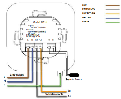
The official manual includes wiring diagrams for both 230V switching mode and volt-free switching mode.
Main Wiring Terminals
| Terminal | Function |
| L | Live |
| N | Neutral |
| A1 / A2 | Boiler enable / switching terminals |
| RT- / RT+ | Remote sensor terminals |
230V Switching Mode
The 230V switching diagram shows:
- 230V supply
- Live
- Neutral
- Earth
- Live return to boiler enable
- Remote sensor connection
This setup is used where the boiler enable connection requires a 230V switched live output.
Volt-Free Switching Mode
The volt-free wiring diagram shows:
- 230V supply input
- LS and LR boiler thermostat connections
- Volt-free switching output
- Remote sensor connection
This setup is used where the boiler provides dedicated thermostat terminals, commonly labelled LS and LR.
Troubleshooting Guide
| Problem | Possible Cause | Recommended Action |
| Display does not turn on | No power supply or wiring issue | Check 230V supply and wiring |
| Heating does not turn on | Set temperature may be lower than room temperature | Turn the dial to a higher temperature |
| Heating switches too often | Differential may be too low | Increase switching differential to 2°C or 3°C |
| Heating response feels slow | Differential may be too high | Reduce switching differential |
| Boiler does not respond | Incorrect wiring mode selected | Check 230V or volt-free wiring diagram |
| Wrong temperature is being measured | Remote sensor may be connected or misplaced | Check remote sensor position and wiring |
| Heating ON icon appears but boiler does not run | Boiler wiring or boiler enable issue | Check boiler manufacturer wiring guidance |
| Remote sensor not working | Sensor wiring issue or incompatible sensor | Check RT- and RT+ terminals and sensor type |
Support and Contact
Heatmiser provides technical support and product information through its official support channels.
Heatmiser UK Ltd Support
Support phone: +44 (0)1254 669090
Website: www.heatmiser.comAddress:
Heatmiser UK Ltd
1–5 Hurstwood Court
Mercer Way
Shadsworth Business Park
Blackburn, Lancashire, BB1 2QU
England