
The Heatmiser Edge is a programmable room thermostat that can work in two modes: Thermostat Mode for heating control and Time Clock Mode for timed output control. It is designed for flush-mounted installation and includes support for remote floor sensing, wireless air sensors, window/door contact sensors, Modbus communication, and multiple wiring options.
The official manual covers installation, mode selection, thermostat programming, accessory pairing, temperature hold, advance mode, frost protection, optional settings, fail safe, Modbus setup, wiring diagrams, time clock operation, battery replacement, and support information.
What Is a Programmable Room Thermostat?
A programmable room thermostat works as both:
| Function | Purpose |
| Programmer | Sets heating ON/OFF periods based on the user’s routine |
| Room thermostat | Measures air temperature and controls heating based on the set temperature |
The manual explains that setting a higher temperature does not make the room heat faster. Heating speed depends on the heating system design and size. The best method is to set the lowest comfortable temperature and allow the thermostat to follow the programmed schedule.
Key Features
The Heatmiser Edge includes:
- Programmable thermostat and time clock modes
- Flush-mounted design
- 35mm minimum back box requirement
- Room and floor temperature sensing
- Wireless air sensor support
- Window/door wireless contact sensor support
- Up to 16 paired accessories
- Temperature hold
- Advance function
- Frost protection
- Holiday mode
- Keypad lock
- Optional 4 or 6 comfort levels
- Modbus interface support
- Fail Safe operation
- Switch live, volt-free, valve, and UH8 wiring options
- Backup lithium battery for timekeeping
Important Safety and Installation Notes
The Heatmiser Edge must be installed carefully and positioned correctly for accurate temperature control.
Installation Do’s and Don’ts
| Do | Don’t |
| Mount the Edge at eye level | Do not install near a direct heat source |
| Read the full instructions before use | Do not press hard on the LCD screen |
| Use a 35mm minimum back box | Do not block airflow with furniture or curtains |
| Follow the correct wiring diagram | Do not wire in a star formation for Modbus |
The wiring diagrams state that the product must only be installed by a qualified electrician and must comply with local installation regulations.
Parts and Controls
The Heatmiser Edge has a large LCD display and side-mounted navigation buttons.
Main Controls
| Control | Function |
| Up button | Raises temperature, time, or setting values |
| Down button | Lowers temperature, time, or setting values |
| Tick button | Confirms selections |
| Left button | Moves left through menus or digits |
| Right button | Moves right through menus or digits |
Main Menu Options
Depending on the selected mode, the display may show:
- Power
- Hold
- Advance
- Holiday / HOLS
- Edit
- Setup
- Clock
- Done
- Cancel
Product Specifications
| Specification | Detail |
| Product model | Heatmiser Edge |
| Product type | Programmable room thermostat / time clock |
| Mounting type | Flush mounted |
| Back box depth | 35mm minimum |
| Modes | Mode 1 Thermostat, Mode 2 Time Clock |
| Default mode | Thermostat |
| Program modes | 5/2 day, 7 day, 24 hour, non-programmable |
| Comfort levels | 4 default, optional 6 levels |
| Wireless accessories | Up to 16 accessories |
| Wireless accessory types | Wireless air sensor, window/door contact |
| Sensor options | Built-in, remote air, floor, built-in + floor, remote air + floor |
| Floor temperature limit | 20°C to 45°C |
| Floor limit default | 28°C |
| Switching differential | 0.5°C, 1.0°C, 2.0°C, 3.0°C |
| Output delay | 00 to 15 minutes |
| Optimum start | Disabled or 1–5 hours |
| DST setting | Disabled or enabled |
| Modbus ID | 01–32 |
| Wiring terminals | A, B, RT1, -, A2, A1, N, L |
| Backup battery | 3V lithium battery for timekeeping |
How to Install the Heatmiser Edge
The Edge is designed to be flush mounted into a wall back box.
Installation Steps
- Loosen the retaining screw
Use a small screwdriver to loosen the screw on the bottom face of the thermostat. - Separate the front plate
Carefully separate the LCD front plate from the back plate. - Place the front plate safely aside
Keep the LCD front plate protected while wiring and mounting. - Connect the wiring
Terminate the Edge according to the wiring diagrams on pages 32–35 of the manual. - Secure the back plate
Screw the back plate securely into the wall back box. - Refit the front plate
Locate the pins in the socket, insert the top edge first, then push in the bottom edge. - Tighten the retaining screw
Secure the thermostat in place.
Mode Select: Thermostat or Time Clock
The Heatmiser Edge can operate in two modes.
| Mode | Function |
| Mode 1 | Thermostat |
| Mode 2 | Time Clock |
Thermostat mode is the default setting.
Important Reset Note
Changing between thermostat and time clock modes resets stored setup parameters. Wireless air sensors and window/door contacts are excluded, but other setup processes must be repeated after restart.
How to Change Mode
- Use Left/Right to highlight the power icon.
- Press and hold the Tick button for 3 seconds.
- The screen goes blank and shows SETUP and CLOCK.
- Press Up or Down to highlight SETUP.
- Hold the Tick button for 10 seconds.
- Use Left/Right to choose:
- Mode 1 = Thermostat
- Mode 2 = Time Clock
- Press Tick to confirm.
- The Edge restarts in the selected mode.
Mode 1: Thermostat Mode
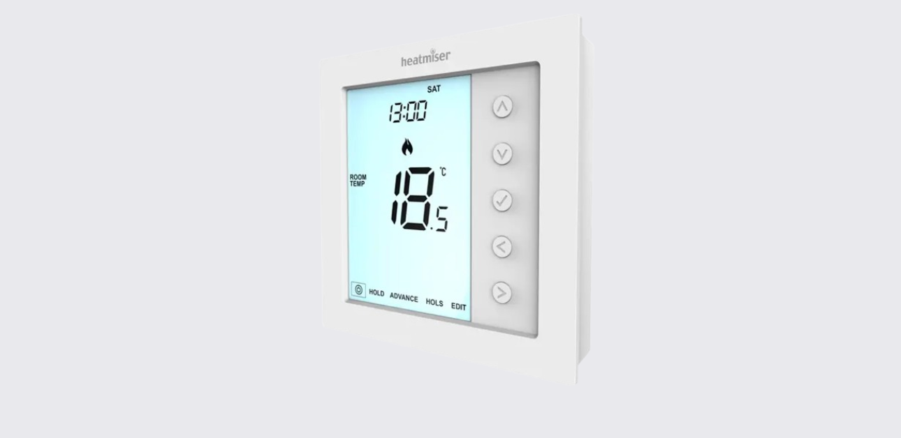
Thermostat Mode LCD Display
| Display Item | Meaning |
| Day indicator | Shows the day of the week |
| Holiday | Thermostat is in holiday mode |
| Clock | Shows time in 24-hour format |
| Flame symbol | Heating is active; flashes during optimum start |
| Frost protection | Frost mode is active or triggered by window/door switch |
| Floor limit symbol | Floor sensor has reached the set floor temperature limit |
| Advanced Until | Next comfort level has been brought forward |
| Hold Left | Temperature hold is active |
| Sensor warning | Wireless sensor or window/door switch signal is missing |
| Floor/Room Temp & Set | Shows sensor mode or set point changes |
| Active status | Shows Preheat or Frost Protection status |
| Program indicator | Shows the comfort period being edited |
| Main menu | Highlighted text shows the selected option |
| Keypad lock | Keypad lock is enabled |
| Temperature | Shows current sensor temperature |
| °C / °F | Temperature format |
| Window icon | Window/door switch is triggered |
| Time/Day/Month/Year | Used for clock, calendar, and holiday settings |
Power On and Off
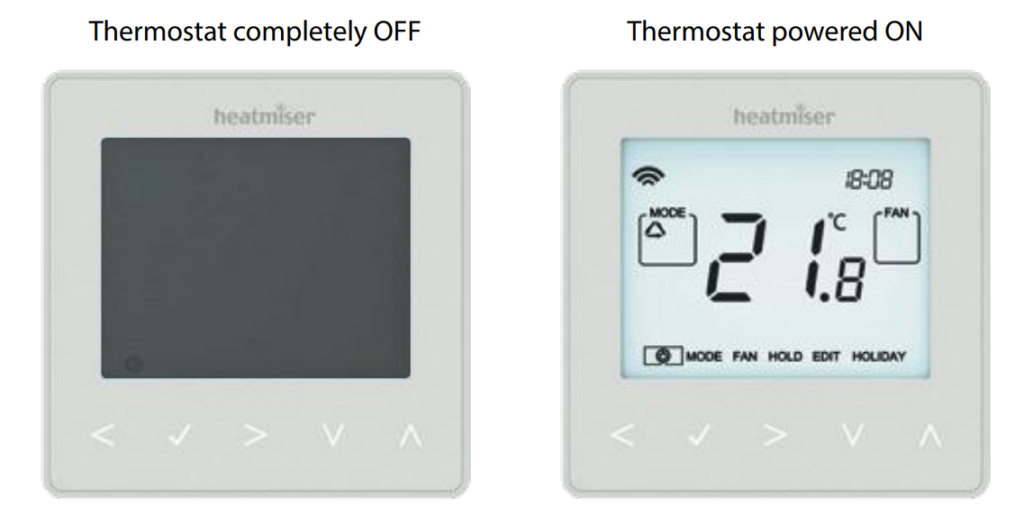
The flame icon appears when the thermostat is calling for heat. If the flame icon is absent, the heating is not required, but the Edge remains active.
Turn the Edge Off
- Scroll to the Power icon.
- Hold the Tick button for about 3 seconds.
- The display goes blank.
- Heating output turns off.
Turn the Edge Back On
Press the Tick button once.
Setting the Time and Date
- Highlight the Power icon.
- Hold the Tick button for 3 seconds.
- The screen shows SETUP and CLOCK.
- Press Up, then Right, to highlight CLOCK.
- Press Tick.
- Use Up/Down to set the hour.
- Press Tick.
- Use Up/Down to set the minutes.
- Repeat for day, month, and year.
- Press Down, then Tick, to return to the main display.
Temperature Display
The Edge can be configured for different sensor options, including:
- Built-in sensor
- Floor sensor
- Built-in sensor + floor sensor
- Wireless air sensor averaging
When both air and floor sensors are used, the room temperature appears by default.
View Floor Temperature
Press and hold the Left and Right arrow keys for 5 seconds. The floor temperature will display briefly.
Pairing Accessories
The Heatmiser Edge can pair with up to 16 accessories.
Supported Accessories
| Accessory | Function |
| Wireless Air Sensor | Adds remote temperature sensing and averages temperature with the thermostat |
| Window/Door Wireless Contact Sensor | Triggers frost protection when a window or door is opened |
How Wireless Air Sensor Works
When a wireless air sensor is added, the Edge averages the temperature between the wireless air sensor and the internal thermostat sensor. If multiple air sensors are paired, the average is calculated across them.
How Window/Door Contact Works
If any paired window or door contact is triggered, the Edge enters Frost Protection Mode. Heating will not resume while the window icon remains on the display.
Pairing Steps
- Highlight the Power icon.
- Hold Tick for 3 seconds to turn off the display.
- Press Up to select Setup, then press Tick.
- Press Down until P appears at the top of the screen.
- Press Tick.
- The thermostat starts a 99-second countdown.
- On the air sensor or window/door contact, hold the pairing button for 5 seconds.
- The LED glows red during pairing.
- When pairing succeeds, the LED turns off.
- The thermostat shows the accessory number, such as 01:P.
Viewing Accessories
To view paired accessories:
- Turn the display off from the power icon.
- Enter Setup.
- Press Down until A appears.
- Press Tick.
- Use Left/Right to scroll through accessories.
A wireless air sensor shows current temperature. A window/door contact shows:
| Display | Meaning |
| OP | Open |
| CL | Closed |
| — | Lost connection |
A low battery warning appears when an accessory reports low power. The manual advises replacing the accessory’s Lithium Cell CR2302 3V battery as soon as possible.
Removing Accessories
Accessories can be removed from either the sensor/contact or the thermostat.
Remove from Sensor or Contact
- Press and hold the pairing/reset button on the sensor or switch for 15 seconds.
- The LED flashes three times.
- The accessory notifies the Edge and leaves the accessory menu.
Remove from Edge Thermostat
- Open the accessory menu.
- Use Left/Right to select the accessory.
- Hold the Tick button for 10 seconds until the accessory disappears.
- Reset the sensor separately.
Comfort Levels and Programming
The Edge supports three program modes and manual control.
| Program Mode | Description |
| 5/2 Day | Weekdays share one schedule, weekends can have another |
| 7 Day | Each day can be programmed separately |
| 24 Hour | Same schedule repeats every day |
| Non-programmable | Basic up/down temperature control |
Default Comfort Levels
| Level | Time | Temperature |
| Level 1 | 07:00 | 21°C |
| Level 2 | 09:00 | 16°C |
| Level 3 | 16:00 | 21°C |
| Level 4 | 22:00 | 16°C |
The thermostat can be configured for up to 6 levels in the feature menu. Unused levels should be set to –:–.
Edit Comfort Levels
- Scroll to EDIT.
- Press Tick.
- Select the day or period.
- Press Tick.
- Select Level 1.
- Set the hour using Up/Down, then press Tick.
- Set the minutes, then press Tick.
- Set the temperature, then press Tick.
- Move to the next level and repeat.
- Set unused levels to –:–.
- Scroll to DONE and press Tick.
Temperature Control
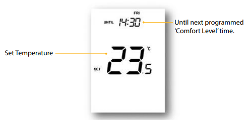
To temporarily adjust the set temperature:
- Press Up or Down.
- The screen shows SET and the desired temperature.
- Adjust with Up/Down.
- Press Tick to confirm.
This temperature override remains active until the next programmed comfort level.
Temperature Hold
Temperature Hold overrides the current program for a selected duration.
Set Temperature Hold
- Scroll to HOLD.
- Press Tick.
- Use Up/Down to set the hold hours.
- Press Tick.
- Use Up/Down to set the hold minutes.
- Press Tick.
- Set the hold temperature.
- Press Tick to confirm.
The screen shows HOLD LEFT, and the countdown runs until the thermostat returns to the normal schedule.
Cancel or Edit Hold
- Scroll to HOLD.
- Press Tick.
- Press Tick while CANCEL is highlighted.
- Or highlight EDIT to change hold settings.
Advance Mode
Advance brings the next comfort level forward before its programmed time.
Enable Advance
- Highlight ADVANCE.
- Press Tick.
- The screen shows ADVANCED UNTIL and the set temperature.
- Press Tick again to confirm.
Multiple advances are not allowed.
Cancel Advance
Highlight ADVANCE and press Tick twice.
Frost Protection
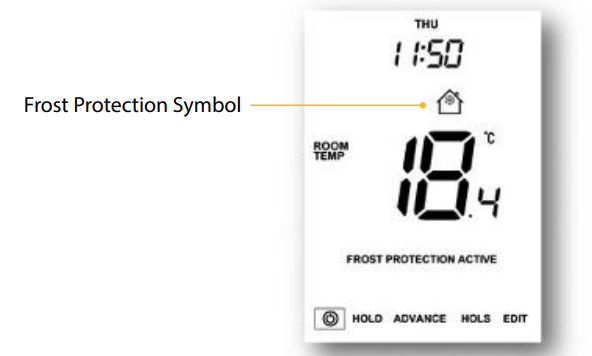
Frost protection only turns heating on if the room temperature drops below the frost protection temperature.
Enable or Disable Frost Protection
- Scroll to the Power icon.
- Press Tick.
- The frost icon toggles on or off.
If heating turns on in frost mode, the flame icon appears.
Locking and Unlocking the Edge
Lock the Edge
- Scroll to Hold.
- Press and hold Tick for 7 seconds.
- The display shows 0000.
- Use Up/Down to enter values.
- Use Left/Right to move between digits.
- Press Tick to confirm.
Unlock the Edge
- Press Tick once.
- Enter the four-digit PIN.
- Press Tick to confirm.
Holiday Mode
Holiday mode works differently depending on the selected mode.
In Thermostat Mode
The Edge reduces the set temperature to the frost mode temperature and maintains it for the holiday period. It then returns to normal programming.
In Time Clock Mode
The timed output turns off during the holiday period and returns to programmed settings afterward.
Set Holiday Mode
- Highlight HOLS.
- Press Tick.
- Set the return time hours.
- Press Tick.
- Set the return time minutes.
- Press Tick.
- Set day, month, and year.
- The display shows Frost Protection Active.
Optional Thermostat Settings
| Feature | Description | Settings |
| A | View accessory status | Information only |
| P | Pair accessories | Countdown 99–00 seconds |
| 01 | Temperature format | °C or °F |
| 02 | Switching differential | 0.5°C, 1.0°C, 2.0°C, 3.0°C |
| 03 | Output delay | 00–15 minutes |
| 04 | Up/down temperature limit | 00°C–10°C |
| 05 | Sensor selection | Built-in, remote air, floor, built-in + floor, remote air + floor |
| 06 | Floor temperature limit | 20°C–45°C |
| 07 | Optimum start | Disabled or 1–5 hours |
| 08 | Rate of change | Information only |
| 09 | Program mode | 5/2, 7 day, 24 hour, non-programmable |
| 10 | Daylight saving time | Disabled or enabled |
| 11 | Communications ID | Modbus 01–32 |
| 12 | Program type | 4 or 6 comfort levels |
Important Floor Heating Note
The manual states that air sensor only must not be used to control electric underfloor heating. For electric underfloor heating, use the floor sensor or both air and floor sensors.
Adjusting Optional Settings
- Highlight the Power icon.
- Hold Tick for 3 seconds.
- The screen shows Setup and Clock.
- Press Up, then press Tick twice to enter the main feature menu.
- Use Up/Down to scroll through features.
- Use Left/Right to change the feature value.
- Press Tick to confirm.
- Select the power icon and press Tick to power on.
Fail Safe and Modbus
Fail Safe
Fail Safe activates when the onboard sensor is disabled and the Edge is relying on one wireless remote sensor for temperature measurement. If connection is lost:
- E2 appears on screen.
- About 12 minutes later, the thermostat enables heat for an initial 12-minute period.
- It then repeats once every hour.
- Fail Safe continues until the wireless sensor reconnects.
Modbus
The Modbus interface allows the thermostat to connect to building management systems or home automation systems.
Key Modbus notes:
- Up to 32 devices can connect to one RS485 adapter.
- A foil twisted pair cable is recommended.
- Connections should be daisy chained, not wired in a star pattern.
- If Edge is the last Modbus device in the chain, move the rear fascia toggle switch to On.
Re-Calibrating the Edge
The manual says the thermostat is factory set and normally does not need recalibration.
Recalibration Steps
- Scroll to the Power icon.
- Hold Tick to turn the display off.
- Press and hold Tick + Down for 10 seconds.
- The current temperature appears.
- Use Up/Down to set the new value.
- Press Tick to confirm.
- Press Tick once to turn the thermostat on.
Error Codes
| Error Code | Meaning | Recommended Action |
| E0 | Internal sensor fault | Contact Heatmiser support or installer |
| E1 | Remote floor probe not connected, wired incorrectly, or faulty | Check floor probe wiring |
| E2 | Wireless air sensor not paired correctly, lost connection, low battery, or faulty | Check sensor pairing and battery |
Wiring Diagram
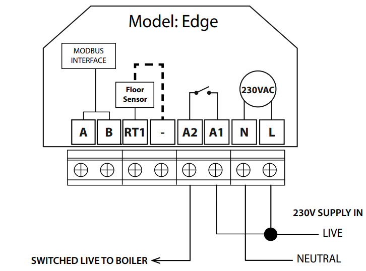
The official manual includes four wiring diagrams.
| Wiring Diagram | Purpose |
| EDGE Switch Live Output | Switched live connection to boiler |
| EDGE Volt Free Output | Volt-free boiler connection for thermostat and time clock modes |
| EDGE to Valve | Heating valve and boiler connection |
| EDGE Switch Live to UH8 | UH8 wiring with floor probe |
Common terminals include A, B, RT1, -, A2, A1, N, and L. The diagrams show Modbus interface terminals, floor sensor connection, 230VAC supply, boiler/valve outputs, and UH8 connections.
Mode 2: Time Clock Mode
Time Clock LCD Display
| Display Item | Meaning |
| Day indicator | Shows day of the week |
| Holiday | Time clock is in holiday mode |
| Clock | Shows time in 24-hour format |
| Advanced Until | Next programmed level has been brought forward |
| Hold Left | Timer override is active |
| Set | Changes are being made |
| Program indicator | Shows the switching period being edited |
| Main menu | Shows the selected option |
| Keypad lock | Keypad is locked |
| Timer status | Shows timed output status |
| Time/Day/Month/Year | Used for calendar and holiday setup |
Setting Switching Times
- Scroll to EDIT.
- Press Tick.
- Use Up/Down to select the day or period.
- Press Tick.
- Select Level 1.
- Set the ON time hours and minutes.
- Set the OFF time hours and minutes.
- Move to Level 2 and repeat.
- Set unused periods to –:–.
- Highlight DONE and press Tick.
Timer Advance
Timer Advance boosts the timed output ON.
Enable Timer Advance
- Highlight ADVANCE.
- Press Tick twice.
- Boost Left and the remaining time appear.
Cancel Timer Advance
Highlight ADVANCE and press Tick twice.
Timer Override
Timer Override changes the timed output ON/OFF state for a selected duration.
Set Timer Override
- Highlight HOLD.
- Press Tick.
- Set override hours.
- Press Tick.
- Set override minutes.
- Press Tick.
- Set output ON or OFF.
- Press Tick to confirm.
Cancel Timer Override
With HOLD highlighted, press Tick twice.
Time Clock Optional Settings
| Feature | Description | Settings |
| Program mode | Sets time clock schedule type | 5/2, 7 day, 24 hour |
| Daylight saving time | Automatic seasonal clock change | Disabled or enabled |
| Communications ID | Modbus ID | 01–32 or disabled |
Replacing the Battery
The Edge contains a 3V lithium battery used only for correct timekeeping during power loss. In most cases, it does not need replacement if the thermostat has constant power.
Battery Replacement Notes
- Remove the battery by pushing back the brass retaining bracket.
- Insert the new battery with the positive side up.
- Place one end under the holding clips and push the other end down against the brass bracket.
- The manual advises replacement by a qualified professional.
Troubleshooting Guide
| Problem | Possible Cause | Recommended Action |
| Heating does not turn on | Set temperature may already be reached | Check the flame icon and raise the set temperature |
| Thermostat is blank | Unit may be powered off or wiring issue | Press Tick or check power supply |
| Floor limit icon appears | Floor probe reached limit | Check floor temperature limit setting |
| Window icon appears | Window/door contact triggered | Close the window/door and check contact sensor |
| Sensor warning flashes | Sensor or contact signal lost | Check accessory pairing and battery |
| E0 appears | Internal sensor fault | Contact support |
| E1 appears | Floor probe issue | Check RT1 and negative terminal wiring |
| E2 appears | Wireless air sensor issue | Re-pair sensor or replace CR2302 battery |
| Keypad does not respond | Keypad lock is active | Enter the four-digit PIN |
| Heating runs during wireless sensor fault | Fail Safe is active | Restore wireless air sensor connection |
| Time clock output does not follow schedule | Wrong program mode or times | Recheck switching times and optional settings |
| Modbus communication fails | Wiring or address issue | Check daisy chain wiring and Communications ID |
Contact Support
Heatmiser provides product support, PDFs, FAQs, technical specifications, and social channels.
Heatmiser Support
Support phone: +44 (0)1254 669090
Website: www.heatmiser.com
Twitter/X: @heatmiseruk
Facebook: facebook.com/thermostats
Official User Manual (PDF)