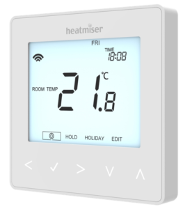
| Field | Details |
| Document Title | Heatmiser neoStat WiFi User Manual |
| Document Type | User Manual |
| Brand Name | Heatmiser |
| Product Name | neoStat WiFi Programmable Thermostat |
| Model Number(s) | neoStat WiFi |
| PDF File Size | 691.8 KB |
| Total Number of Pages | 44 |
| Languages Covered | English |
Heatmiser Programmable Thermostat neoStat WiFi
The Heatmiser neoStat WiFi is a smart programmable room thermostat designed to control heating systems through temperature settings, daily schedules, and wireless connectivity. It connects directly to a home Wi-Fi network, allowing heating to be managed through the Heatmiser neoApp without requiring a separate neoHub.
The thermostat features an LCD display, five touch-sensitive navigation keys, an approach sensor, programmable heating schedules, frost protection, temperature hold, holiday programming, and keypad locking. It also supports Apple HomeKit for compatible smart home control and Siri voice commands.
The neoStat WiFi operates from a 230V AC power supply and supports different heating control connections, including switched-live boilers, volt-free boiler connections, heating valves, and the Heatmiser UH8 wiring center.
Two operating modes are available:
- Mode 1 – Thermostat: Controls heating according to room or floor temperature and programmable comfort levels.
- Mode 2 – Time Clock: Controls a compatible timed electrical output using programmed ON and OFF switching times.
The thermostat supports built-in air sensing, remote air sensing, floor temperature sensing, and combined sensor arrangements. For electric underfloor heating applications, the floor sensor must be used either independently or together with an air sensor.
Product Overview and Technical Specifications
The neoStat WiFi belongs to the Heatmiser neoStat Series and provides programmable temperature control with direct Wi-Fi connectivity.
| Specification | Details |
| Brand | Heatmiser |
| Model | neoStat WiFi |
| Product Series | neoStat Series |
| Product Type | Wi-Fi Programmable Room Thermostat |
| Power Supply | 230V AC |
| Display | LCD |
| Controls | Five touch-sensitive navigation keys |
| Approach Sensor | Supported |
| Installation Type | Flush-mounted |
| Minimum Back Box Depth | 35 mm |
| Operating Modes | Mode 1: Thermostat; Mode 2: Time Clock |
| Default Operating Mode | Thermostat |
| Wireless Connectivity | Direct Wi-Fi connection |
| Wi-Fi Operating Frequency | 2.412–2.472 GHz |
| Wi-Fi Output Power | 17.0 dBm (802.11) |
| Mobile App | Heatmiser neoApp |
| Apple HomeKit | Supported |
| Siri Voice Control | Supported through HomeKit |
| Heating Programs | Weekday/Weekend, 7 Day, 24 Hour |
| Non-Programmable Operation | Supported |
| Default Programming Mode | Weekday/Weekend |
| Comfort Levels | Four per programmed day or day group |
| Temperature Units | Celsius (°C) or Fahrenheit (°F) |
| Sensor Options | Built-in air, remote air, floor, or combined sensors |
| Default Floor Probe Type | 10K |
| Additional Compatible Probe Types | 12K, 15K |
| Switching Differential | 0.5°C, 1°C, 2°C, or 3°C |
| Default Switching Differential | 1°C |
| Frost Protection Range | 7–17°C |
| Default Frost Protection Temperature | 12°C |
| Output Delay | 0–15 minutes |
| Floor Temperature Limit | 20–45°C |
| Default Floor Temperature Limit | 28°C |
| Optimum Start | 0–5 hours |
| Temperature Hold | Supported |
| Holiday Mode | Supported |
| Keypad Lock | Four-digit PIN |
| Wi-Fi Reset | Supported |
| Factory Reset | Supported |
Understanding the Programmable Room Thermostat
The neoStat WiFi combines the functions of a heating programmer and a room thermostat.
The thermostat measures the current temperature and requests heating when the measured temperature falls below the selected target. When the required temperature is reached, heating demand stops.
Its programming function allows different temperatures to be maintained at different times of the day.
How Temperature Settings Affect Heating
Increasing the thermostat’s set temperature does not cause the heating system to warm a room faster.
Heating speed depends on the heating system’s design and capacity.
Setting a higher target temperature causes the system to continue heating until that temperature is reached.
Similarly, lowering the target temperature does not make a room cool faster. It changes the temperature the thermostat is instructed to maintain.
Choosing a Comfortable Temperature
A practical way to establish a suitable temperature is to begin with a setting of approximately 18°C and increase it gradually by 1°C each day until the desired comfort level is achieved.
Once a suitable temperature has been selected, the thermostat can maintain it according to the programmed heating schedule.
Unnecessarily high target temperatures can increase heating energy consumption.
Thermostat Position and Airflow
The thermostat needs unrestricted airflow to measure the surrounding air temperature accurately.
It should not be covered with curtains or obstructed by furniture.
Nearby electric heaters, televisions, and wall or table lamps may also affect temperature readings.
Parts, Components, and Touch Controls
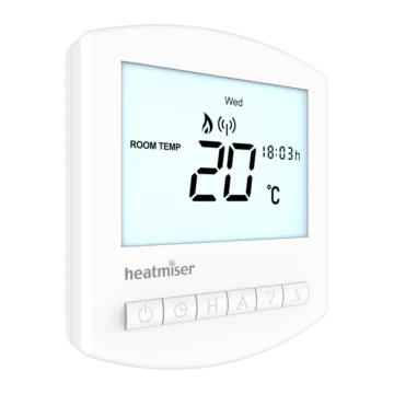
The neoStat WiFi features an LCD display and five touch-sensitive navigation keys located beneath the screen.
The thermostat has a removable front panel, mounting back plate, retaining screw, and electrical connection terminals.
Main Components
| Component | Function |
| LCD Display | Shows temperature, time, heating demand, menus, and operating information. |
| Left Arrow | Moves left through menu options. |
| Tick / Confirm | Opens selected options, confirms settings, and activates functions. |
| Right Arrow | Moves right through menu options. |
| Down Arrow | Decreases temperatures and adjustable values. |
| Up Arrow | Increases temperatures and adjustable values. |
| Approach Sensor | Illuminates the display and touch controls when approached. |
| Front Panel | Contains the display and controls. |
| Back Plate | Secures the thermostat to the wall back box. |
| Retaining Screw | Secures the front panel to the back plate. |
| Electrical Terminals | Connect the power supply, heating control, and optional temperature probes. |
Touch Control Buttons
| Button | Function |
| Left (◀) | Moves left through menus and available selections. |
| Tick (✓) | Confirms settings and activates the highlighted function. |
| Right (▶) | Moves right through menus and selections. |
| Down (▼) | Decreases the selected temperature, time, or setting. |
| Up (▲) | Increases the selected temperature, time, or setting. |
Some functions require Tick to be held for several seconds or combined with another button.
Understanding the LCD Display
The LCD shows the current temperature, heating demand, wireless connection status, time, and programmed settings.
Thermostat Mode Display Indicators
| Indicator | Meaning |
| Wi-Fi Symbol | Indicates connection to the home Wi-Fi network. |
| Day Indicator | Shows the current day of the week. |
| Frost Protection Symbol | Indicates that frost protection is enabled. |
| Flame Symbol | Indicates that the thermostat is requesting heating. |
| Flashing Flame Symbol | Indicates that Optimum Start is active. |
| Holiday Symbol | Indicates Holiday Mode. |
| Floor Limit Symbol | Indicates that the floor probe has reached the configured temperature limit. |
| ROOM TEMP | Identifies the room temperature reading. |
| FLOOR TEMP | Identifies the floor temperature reading. |
| SET | Appears when changing the target temperature or settings. |
| Program Indicator | Shows the comfort period being configured. |
| Main Menu | Identifies the highlighted function. |
| Keypad Lock Symbol | Indicates that the keypad is locked. |
| Temperature Display | Shows the measured temperature. |
| °C / °F | Shows the selected temperature unit. |
| HOLD LEFT | Shows the remaining duration of a temperature hold. |
| Time/Day/Month/Year | Displays clock and calendar information. |
Heating Demand Indicator
The flame icon appears when the thermostat is requesting heat.
When the flame icon is absent, the thermostat does not currently need heating to maintain the selected temperature.
The flame icon flashes when Optimum Start is operating.
Wi-Fi Connection Indicator
The Wi-Fi symbol appears when the thermostat is connected to the home Wi-Fi network.
Approach Sensor
The neoStat WiFi uses an approach sensor to detect when someone moves toward the thermostat.
As a person approaches, the touch controls and display illuminate.
This makes the temperature and controls easier to view when adjusting the heating system in a dark room.
Safety Instructions and Installation Requirements
The neoStat WiFi operates using a 230V AC mains electrical supply.
The thermostat must only be installed by a qualified electrician, and installation must comply with local electrical regulations.
Important Installation Precautions
- Mount the thermostat at eye level.
- Avoid installing it close to direct heat sources.
- Do not apply excessive pressure to the LCD screen because permanent damage may occur.
- Use a recessed wall back box with a minimum depth of 35 mm.
- Follow the wiring diagram for the connected boiler, heating valve, or wiring center.
- Follow the boiler manufacturer’s electrical connection instructions.
- Use the appropriate temperature sensor configuration for the heating system.
Electric Underfloor Heating Sensor Requirement
The built-in air sensor alone must not be used to control electric underfloor heating.
For electric underfloor heating, the thermostat must use:
- The floor temperature sensor alone, or
- A combined air and floor sensor configuration.
The floor sensor provides floor temperature regulation or limiting, depending on the selected configuration.
Installing the neoStat WiFi Thermostat
The neoStat WiFi is designed for flush mounting into a recessed back box.
A minimum back box depth of 35 mm is required.
Step 1: Remove the Front Panel
- Locate the retaining screw on the bottom edge of the thermostat.
- Use a small screwdriver to loosen the screw slightly.
- Carefully separate the front section from the back plate.
- Place the front panel somewhere safe.
Step 2: Connect the Electrical Wiring
The thermostat must be connected according to the manufacturer’s wiring diagram.
The manual includes diagrams for:
- Switched-live boiler connections.
- Volt-free boiler connections.
- Heating valve connections.
- Heatmiser UH8 wiring center connections.
- Time Clock Mode connections.
The correct diagram must be selected for the installed equipment.
Step 3: Secure the Back Plate
- Position the thermostat back plate against the recessed wall back box.
- Align the mounting holes.
- Screw the back plate securely into the box.
Step 4: Reattach the Front Panel
- Position the thermostat front panel against the mounted back plate.
- Carefully clip the front panel into place.
- Tighten the retaining screw.
The installation procedure is illustrated on PDF pages 6–7.
Selecting the Operating Mode
The neoStat WiFi supports two operating modes.
| Mode | Function |
| Mode 1 | Thermostat |
| Mode 2 | Time Clock |
Thermostat Mode is the factory default.
Mode 1: Thermostat
Thermostat Mode controls heating according to the measured temperature and selected target.
It supports programmable comfort levels, temperature adjustment, Temperature Hold, Frost Protection, and Holiday Mode.
Mode 2: Time Clock
Time Clock Mode switches a compatible electrical output according to programmed ON and OFF times.
It operates as a timer rather than a temperature-regulating thermostat.
How to Change the Operating Mode
- Use Left and Right to highlight the Power symbol.
- Press and hold Tick for 3 seconds.
- SETUP becomes highlighted.
- Press and hold Tick for 10 seconds.
- Use Left and Right to select the required mode.
- Select 1 for Thermostat or 2 for Time Clock.
- Press Tick to confirm.
The neoStat WiFi returns to the main display for the selected mode.
Important: This process uses the factory reset sequence. Previously configured setup and pairing parameters are canceled and must be configured again where required.
Connecting the neoStat WiFi to a Wi-Fi Network
The neoStat WiFi connects directly to the home Wi-Fi network through its own temporary Wi-Fi hotspot.
Setup is completed using the Heatmiser neoApp.
Step 1: Install the Heatmiser neoApp
- Download the Heatmiser neoApp onto a smartphone or tablet.
- Open the app.
- Sign in with an existing account or register a new account.
Step 2: Add the neoStat WiFi
- Open the Locations screen.
- Tap the + icon.
- Select neoStat WiFi from the available device options.
- Enter a name for the location, such as Home.
Step 3: Connect to the Thermostat Hotspot
- Follow the app’s connection instructions.
- Connect the smartphone or tablet directly to the thermostat’s neoStat WiFi hotspot.
- Continue the setup process in the app.
Step 4: Select the Home Wi-Fi Network
- After connecting to the thermostat hotspot, choose the required home Wi-Fi network.
- Follow the app instructions to connect the thermostat to that network.
- Enter a name for the thermostat’s room, such as Living Room.
- Complete the remaining setup steps in the neoApp.
Once connected, the thermostat can be controlled using the app.
Wi-Fi Connection Status
The Wi-Fi symbol appears on the thermostat display when it is connected to the home network.
The direct connection process is illustrated on PDF page 10.
Mode 1: Thermostat Operation
Mode 1 provides temperature-based heating control.
The thermostat can maintain a selected temperature manually or operate according to programmed comfort levels.
Available functions include:
- Room temperature monitoring.
- Floor temperature monitoring.
- Programmable heating schedules.
- Manual temperature adjustments.
- Temperature Hold.
- Frost Protection.
- Holiday Mode.
- Keypad locking.
- Optimum Start.
- Advanced sensor and heating settings.
Turning the Thermostat On and Off
How to Turn the Thermostat Off
- Use Left and Right to highlight the Power symbol.
- Press and hold Tick for approximately 3 seconds.
- Continue until the display becomes blank.
The display and heating output are switched off.
How to Turn the Thermostat On
Press Tick once.
The thermostat returns to its normal operating display.
Understanding the Flame Indicator
When the flame icon appears, the thermostat is requesting heating.
When the icon is absent, heating is not currently required to achieve the selected temperature.
The thermostat remains active unless it has been switched off.
Room and Floor Temperature Display
The neoStat WiFi can be configured to use different temperature sensors.
Available arrangements include:
- Built-in air sensor.
- Remote air sensor.
- Floor sensor.
- Built-in air and floor sensors.
- Remote air and floor sensors.
Room Temperature Display
When an air temperature sensor is active, the screen displays ROOM TEMP.
Floor Temperature Display
When floor temperature is being displayed, the screen shows FLOOR TEMP.
How to View the Floor Temperature
When both air and floor sensors are configured, room temperature appears by default.
To view floor temperature:
- Press and hold Left and Right together.
- Continue holding for 5 seconds.
- The floor temperature appears on the display.
Setting the Clock and Calendar
The correct clock and calendar settings are needed for scheduled heating and holiday operation.
How to Set the Clock
- Use Left and Right to highlight the Power symbol.
- Press and hold Tick to turn off the display.
- Use Right to select CLOCK.
- Press Tick.
- Use Up and Down to set the year.
- Press Tick to confirm.
- Repeat the procedure for the month, date, and time.
- Press Tick to confirm the completed settings.
- Use Down to highlight the Power symbol.
- Press Tick to turn the thermostat on.
Heating Programs and Comfort Levels
The neoStat WiFi supports three programmable heating schedules and a non-programmable operating option.
Available Programming Modes
| Programming Mode | Description |
| Weekday/Weekend | Separate schedules for weekdays and weekends. |
| 7 Day | Individual heating schedules for each day. |
| 24 Hour | One heating schedule repeated every day. |
| Non-Programmable | Manual temperature control without scheduled comfort periods. |
Once the thermostat is connected online, its programming mode is configured through the neoApp.
Default Comfort Levels
The neoStat WiFi is supplied with four programmed comfort periods.
| Comfort Period | Starting Time | Temperature |
| WAKE | 07:00 | 21°C |
| LEAVE | 09:00 | 16°C |
| RETURN | 16:00 | 21°C |
| SLEEP | 22:00 | 16°C |
Each comfort level maintains its target temperature until the next programmed period begins.
Weekday/Weekend Programming
This mode provides four comfort levels for Monday through Friday and four separate levels for Saturday and Sunday.
7 Day Programming
In 7 Day Mode, each day can have four independently configured comfort levels.
24 Hour Programming
In 24 Hour Mode, the same four comfort periods repeat every day.
Programming the Heating Comfort Levels
The heating schedule can be changed directly using the thermostat controls.
How to Program Comfort Levels
- Use Left and Right to highlight EDIT.
- Press Tick.
- Use Left and Right to select the required day or day group.
- Press Tick.
- WAKE flashes with its current time and temperature.
- Press Tick to edit WAKE.
- Use Up and Down to set the hour.
- Press Tick.
- Use Up and Down to set the minutes.
- Press Tick.
- Use Up and Down to select the required temperature.
- Press Tick to confirm.
- Press Right to move to LEAVE.
- Press Tick to edit the LEAVE settings.
- Repeat the procedure for RETURN and SLEEP.
- Highlight DONE using Left and Right.
- Press Tick to save the program.
Disabling Unused Comfort Periods
An unused comfort period can be disabled by setting its time to –:–.
The thermostat skips that period and continues to the next programmed comfort level.
Adjusting the Set Temperature
The Up and Down buttons allow the target temperature to be changed directly.
How to Change the Temperature
- Press Up or Down.
- SET appears with the current target temperature.
- Use Up and Down to select the required temperature.
- Press Tick to confirm.
The thermostat returns to its normal display.
How Long Does a Manual Temperature Change Last?
When a heating program is active, the new target temperature remains in effect until the next programmed comfort level.
The thermostat then returns to the scheduled temperature.
Temperature Hold Function
Temperature Hold temporarily overrides the heating program and maintains a different temperature for a selected duration.
How to Activate Temperature Hold
- Use Left and Right to highlight HOLD.
- Press Tick.
- Use Up and Down to select the required hold duration.
- Press Tick.
- Use Up and Down to select the required hold temperature.
- Press Tick to confirm.
The display shows HOLD LEFT and the remaining hold duration.
When the countdown ends, the thermostat returns to the normal heating program.
How to Cancel Temperature Hold
- Highlight HOLD.
- Press Tick.
- When CANCEL is highlighted, press Tick again.
The temporary hold is canceled.
Locking and Unlocking the Thermostat
The neoStat WiFi includes a keypad lock controlled by a four-digit PIN.
How to Lock the Thermostat
- Use Left and Right to highlight HOLD.
- Press and hold Tick for 10 seconds.
- The display shows 0000.
- Use Up and Down to enter the first two PIN digits.
- Press Tick.
- Use Up and Down to enter the remaining two digits.
- Press Tick to confirm.
The keypad lock symbol appears.
How to Unlock the Thermostat
- Press Tick once.
- The display shows 00:00.
- Use Up and Down to enter the first two digits of the previously configured PIN.
- Press Tick.
- Enter the remaining two digits.
- Press Tick.
The keypad unlocks and returns to the normal display.
Frost Protection Mode
Frost Protection maintains a reduced temperature when normal heating is not required.
The thermostat requests heating only when the measured temperature falls below the selected frost protection temperature.
How to Activate Frost Protection
- Use Left and Right to highlight the Power symbol.
- Press Tick once.
The frost protection symbol appears on the display.
When heating is required during Frost Protection, the flame icon appears.
How to Cancel Frost Protection
- Highlight the Power symbol.
- Press Tick again.
The frost protection symbol disappears.
Frost Protection Settings
| Setting | Temperature |
| Minimum | 7°C |
| Maximum | 17°C |
| Factory Default | 12°C |
The frost protection temperature can be changed through optional Feature 03.
Holiday Mode
Holiday Mode temporarily changes the normal heating program for a selected period.
In Thermostat Mode, the target temperature is reduced to the configured frost protection temperature.
In Time Clock Mode, the timed output is maintained in the OFF state.
How to Activate Holiday Mode
- Use Left and Right to highlight HOLIDAY.
- Press Tick.
- Use Up and Down to select the holiday ending year.
- Press Tick.
- Select the month.
- Press Tick.
- Repeat the procedure for the ending date and time.
- Press Tick to confirm.
The holiday begins immediately.
The thermostat automatically returns to its normal program at the configured ending date and time.
How to Cancel Holiday Mode
- Highlight HOLIDAY.
- Press Tick.
- When CANCEL is highlighted, press Tick again.
Holiday Mode is canceled.
Advanced Thermostat Settings
The neoStat WiFi includes optional settings for switching differential, temperature limits, sensor configuration, floor temperature protection, and heating schedules.
Most settings can remain at their factory defaults.
How to Open the Optional Settings
- Use Left and Right to highlight the Power symbol.
- Press and hold Tick for 3 seconds.
- SETUP is highlighted.
- Press Tick once.
- The feature number and setting value appear.
- Use Up and Down to select the required feature.
- Use Left and Right to change the setting.
- Press Tick to confirm and exit.
Optional Settings Reference Table
| Feature | Description | Available Settings |
| 01 | Pairing | Used to connect neoStat WiFi to the neoApp |
| 02 | Switching Differential | 0.5°C, 1°C, 2°C, 3°C; Default: 1°C |
| 03 | Frost Protection Temperature | 7–17°C; Default: 12°C |
| 04 | Output Delay | 0–15 minutes; Default: 0 |
| 05 | Up/Down Temperature Limit | 0–10°C; Default: 0 |
| 06 | Sensor Selection | Built-in, remote air, floor, or combined sensors |
| 07 | Floor Temperature Limit | 20–45°C; Default: 28°C |
| 08 | Optimum Start | 0–5 hours; Default: 0 |
| 09 | Rate of Change | Calculated minutes required for a 1°C rise |
| 10 | Not Used | — |
| 11 | Not Used | — |
| 12 | Programming Mode | Non-Programmable, Weekday/Weekend, 7 Day, 24 Hour |
| 13 | Temperature Format | Celsius or Fahrenheit |
Feature 01: Pairing
Feature 01 is used during connection of the neoStat WiFi to the Heatmiser neoApp.
The thermostat uses a direct Wi-Fi connection rather than requiring a separate neoHub.
Feature 02: Switching Differential
Switching Differential determines how far the measured temperature must fall below the target before heating starts.
For example, with a target temperature of 20°C:
- A 1°C differential activates heating at 19°C and stops it at 20°C.
- A 2°C differential activates heating at 18°C and stops it at 20°C.
The factory default is 1°C.
Feature 03: Frost Protection Temperature
This setting determines the temperature maintained while Frost Protection Mode is active.
The available range is 7–17°C.
The default is 12°C.
Feature 04: Output Delay
Output Delay helps prevent rapid switching of the heating output.
The range is 0–15 minutes.
The default setting is 0, meaning no additional delay is applied.
Feature 05: Temperature Adjustment Limit
This feature restricts the amount of temperature adjustment available through Up and Down.
The restriction also applies while the keypad is locked, allowing limited temperature control.
The adjustable range is 0–10°C.
Feature 06: Temperature Sensor Selection
The thermostat supports five temperature sensor configurations.
| Setting | Sensor Mode |
| 00 | Built-in Air Sensor (Default) |
| 01 | Remote Air Sensor |
| 02 | Floor Sensor Only |
| 03 | Built-in Air and Floor Sensor |
| 04 | Remote Air and Floor Sensor |
When both air and floor sensors are selected, the floor sensor acts as a temperature-limiting sensor.
The air-only sensor setting must not be used for electric underfloor heating.
Feature 07: Floor Temperature Limit
The floor temperature limit is available when Sensor Selection is configured as 03 or 04.
The adjustable range is 20–45°C.
The factory default is 28°C.
The floor sensor limits temperature to help prevent excessive floor heating.
Feature 08: Optimum Start
Optimum Start calculates when heating should begin so that the programmed temperature is reached at the required time.
The thermostat uses the observed heating rate to estimate the warm-up period.
The adjustable range is 0–5 hours.
The factory default is 0.
Feature 09: Rate of Change
Rate of Change represents the number of minutes the thermostat calculates are needed to increase temperature by 1°C.
For example, a value of 20 represents an estimated 20 minutes to raise the temperature by 1°C.
This information is used by Optimum Start.
Feature 12: Programming Mode
| Setting | Programming Mode |
| 00 | Non-Programmable |
| 01 | Weekday/Weekend (Default) |
| 02 | 7 Day |
| 03 | 24 Hour |
Feature 13: Temperature Format
The temperature display can be changed between Celsius and Fahrenheit.
| Setting | Unit |
| 00 | Celsius (Default) |
| 01 | Fahrenheit |
Changing the Floor Sensor Probe Type
The neoStat WiFi is configured by default for a 10K floor sensor probe.
It also supports 12K and 15K probe types.
Compatible Floor Probe Values
| Setting | Probe Type |
| 10 | 10K |
| 12 | 12K |
| 15 | 15K |
How to Change the Floor Probe Type
- Use Left and Right to highlight the Power symbol.
- Press and hold Tick to turn off the display.
- Press and hold Up and Down together for 5 seconds.
- The probe selection screen appears.
- Use Left and Right to select 10, 12, or 15.
- Press Tick to confirm.
The thermostat returns to the main display with the selected probe type.
Important: The manufacturer specifies that this procedure should only be performed by an experienced technician who has accurately verified the installed probe value.
Recalibrating the Thermostat
The neoStat WiFi includes a temperature recalibration function.
How to Recalibrate the Temperature
- Use Left and Right to highlight the Power symbol.
- Press and hold Tick to turn off the display.
- Press and hold Tick and Down together for 10 seconds.
- The current temperature appears.
- Use Up and Down to select the new temperature value.
- Press Tick to confirm.
- The display becomes blank.
- Use Down to highlight the Power symbol.
- Press Tick to turn the thermostat on.
Error Codes and Troubleshooting
The neoStat WiFi displays error codes when a temperature sensor fault is detected during thermostat operation.
Error Code Reference
| Error Code | Meaning | Recommended Action |
| E0 | Internal temperature sensor fault | Obtain technical assistance. |
| E1 | Remote floor probe disconnected, incorrectly wired, or faulty | Have the floor probe and connections checked. |
| E2 | Remote air probe disconnected, incorrectly wired, or faulty | Have the remote air probe and connections checked. |
Error E0: Internal Sensor Fault
E0 indicates that the thermostat’s internal temperature sensor has developed a fault.
Technical assistance should be obtained from the manufacturer or an appropriate service professional.
Error E1: Remote Floor Sensor Fault
E1 indicates a problem with the remote floor temperature probe.
Possible conditions include:
- The floor probe has not been connected.
- The floor probe is incorrectly wired.
- The floor probe is faulty.
The floor probe and its wiring require assessment.
Error E2: Remote Air Sensor Fault
E2 indicates a problem with the remote air temperature probe.
Possible conditions include:
- The remote air probe has not been connected.
- The remote air probe is incorrectly wired.
- The remote air probe is faulty.
The sensor connection and probe condition require checking.
Common Operating Checks
| Symptom or Indicator | Meaning or Recommended Action |
| Wi-Fi symbol is absent | Check the thermostat’s Wi-Fi connection and setup. |
| Thermostat needs to join a different Wi-Fi network | Use the Wi-Fi Reset procedure to reactivate its hotspot. |
| Flame icon is absent | There is no current heating demand. |
| Flame icon flashes | Optimum Start is operating. |
| Frost icon appears | Frost Protection Mode is active. |
| HOLD LEFT appears | Temperature Hold or Timer Override is active. |
| Keypad lock icon appears | The thermostat is locked and requires the configured PIN. |
| Floor limit icon appears | The configured floor temperature limit has been reached. |
| E0 appears | Internal temperature sensor fault. |
| E1 appears | Remote floor sensor connection or probe fault. |
| E2 appears | Remote air sensor connection or probe fault. |
Checking an Unexpected Heating Schedule
When the heating does not follow the expected schedule:
- Check the current operating mode.
- Review the selected programming mode.
- Check the programmed comfort levels.
- Check whether Temperature Hold is active.
- Check whether Frost Protection or Holiday Mode is active.
- Review any displayed sensor error code.
Mode 2: Time Clock Operation
Mode 2 allows the neoStat WiFi to operate as a programmable time clock.
In this mode, the electrical output is controlled using scheduled ON and OFF times instead of room temperature regulation.
Time Clock LCD Display
The Time Clock display shows the current time, switching status, and any active override or holiday setting.
Time Clock Display Indicators
| Indicator | Meaning |
| Wi-Fi Symbol | Indicates connection to the home Wi-Fi network. |
| Day Indicator | Displays the current day. |
| Holiday Symbol | Indicates Holiday Mode. |
| SET | Appears when changing settings. |
| Program Indicator | Identifies the switching period being programmed. |
| Main Menu | Shows the highlighted function. |
| Keypad Lock Symbol | Indicates that the keypad is locked. |
| TIMER ON / TIMER OFF | Shows the current timed output status. |
| HOLD LEFT | Displays the remaining timer override duration. |
| Time/Day/Month/Year | Shows clock and calendar information. |
Programming Time Clock Switching Times
The time clock supports four programmed switching periods per day or day group.
Each period contains an ON time and an OFF time.
Time Clock Programming Modes
| Mode | Description |
| Weekday/Weekend | Four ON/OFF periods for weekdays and four separate periods for weekends. |
| 7 Day | Four independently programmed ON/OFF periods for each day. |
| 24 Hour | The same switching schedule repeats every day. |
How to Set the Switching Times
- Use Left and Right to highlight EDIT.
- Press Tick.
- Use Left and Right to select the day or day group.
- Press Tick.
- Switching period 1 flashes and its ON time appears.
- Press Down to view the existing OFF time if required.
- Select the switching period and press Tick.
- Use Up and Down to set the ON hour.
- Press Tick.
- Use Up and Down to set the ON minutes.
- Press Tick.
- Use Up and Down to set the OFF hour.
- Press Tick.
- Use Up and Down to set the OFF minutes.
- Press Tick.
- Press Right to move to switching period 2.
- Repeat the procedure for the remaining periods.
- Highlight DONE.
- Press Tick to save all changes.
Disabling Unused Switching Periods
Unused switching periods can be disabled by setting their time to –:–.
The time clock ignores those periods.
Timer Override
Timer Override temporarily activates the timed output for a selected duration.
How to Activate Timer Override
- Use Up and Down to select the required override duration.
- For example, select 02:00 for a two-hour override.
- Press Tick to confirm.
The display shows HOLD LEFT and the remaining time.
The output returns to its normal programmed operation when the override duration expires.
Time Clock Optional Settings
Time Clock Mode includes settings for pairing and scheduling.
| Feature | Description | Available Settings |
| 01 | Pairing | Used to connect the neoStat WiFi to the app |
| 02 | Programming Mode | Weekday/Weekend, 7 Day, 24 Hour |
Time Clock Programming Mode Settings
| Setting | Programming Mode |
| 01 | Weekday/Weekend (Default) |
| 02 | 7 Day |
| 03 | 24 Hour |
Time Clock Mode Wiring Diagram
The Time Clock Mode wiring diagram is located on PDF page 39 (printed manual page 38).
It shows the neoStat WiFi connected to a 230V AC mains supply and a volt-free switching output.
Time Clock Terminal Identification
| Terminal | Function |
| RT2 | Remote air probe terminal |
| RT1 | Remote floor probe terminal |
| – | Sensor common connection |
| A2 | Switched output terminal |
| A1 | Switching common terminal |
| N | Neutral mains supply |
| L | Live mains supply |
Volt-Free Output
The manufacturer illustrates A1 and A2 as the volt-free output connections.
230V Switched Output
For a 230V output on A2, the wiring diagram specifies a link between the live supply and A1.
The exact electrical connections must follow the manufacturer’s diagram.
All wiring must be completed by a qualified electrician in accordance with local electrical regulations.
neoStat WiFi Wiring Diagrams
The manufacturer provides four electrical connection diagrams for Thermostat Mode and one for Time Clock Mode.
The diagrams show the 230V AC supply, heating switching contacts, optional temperature probes, and connected equipment.
Thermostat Terminal Identification
The terminal strip is labeled:
RT2 — RT1 — – — A2 — A1 — N — L
| Terminal | Function |
| RT2 | Remote air sensor connection |
| RT1 | Floor temperature sensor connection |
| – | Common sensor connection |
| A2 | Heating control switching terminal |
| A1 | Heating control switching terminal |
| N | Neutral mains supply |
| L | Live mains supply |
The exact function of the switching terminals depends on the connected heating equipment and its wiring arrangement.
Switched-Live Boiler Wiring
The switched-live boiler wiring diagram is located on PDF page 30 (printed manual page 29).
The diagram shows the neoStat WiFi connected to a boiler requiring a switched-live control signal.
Connections shown include:
- Live mains supply.
- Neutral mains supply.
- Heating control switching terminals.
- Switched-live connection to the boiler.
The final boiler connection arrangement must follow the boiler manufacturer’s wiring diagram.
Volt-Free Boiler Wiring
The volt-free boiler wiring diagram is located on PDF page 31 (printed manual page 30).
This arrangement shows the thermostat connected to the boiler’s room thermostat terminals through a volt-free contact.
Boiler Terminal Identification
The diagram identifies the boiler connections as:
- LS
- LR
These are normally the boiler’s room thermostat connection terminals.
The terminal labels may vary between boiler manufacturers.
The boiler manufacturer’s wiring diagram must be consulted before completing the connections.
Heating Valve Wiring
The heating valve wiring diagram is located on PDF page 32 (printed manual page 31).
The diagram illustrates a heating valve connected to the thermostat’s switching terminals.
It also shows the valve’s auxiliary switching connections to the boiler.
Connections illustrated include:
- Live supply.
- Neutral supply.
- Heating valve.
- Valve auxiliary switch.
- Boiler room thermostat connections.
The final wiring arrangement must follow the boiler and valve manufacturers’ instructions.
Connecting the neoStat WiFi to a UH8 Wiring Center
The UH8 wiring center connection diagram is located on PDF page 33 (printed manual page 32).
The diagram illustrates the neoStat WiFi connected to the Heatmiser UH8 wiring center.
It also shows optional remote floor and remote air temperature probe connections.
UH8 Connection Information
The illustrated UH8 terminals include:
- L
- Zone connection terminals 1 and 2
- E
- N
- SL
The thermostat’s mains and switched control connections are shown separately from its remote sensor connections.
Optional Remote Floor Sensor
The floor sensor is illustrated connected through the appropriate RT1 and sensor common terminals.
Optional Remote Air Sensor
The remote air sensor is illustrated connected through RT2 and the sensor common terminal.
The original diagram must be followed for the exact connections.
Resetting the neoStat WiFi Connection
The neoStat WiFi includes a Wi-Fi Reset function that reactivates its Wi-Fi hotspot.
This procedure is different from a complete factory reset.
How to Reset the Wi-Fi Connection
- Use Left and Right to highlight the Power symbol.
- Press and hold Tick to switch off the display.
- SETUP is highlighted.
- Press Tick once.
- Feature 01 flashes in the upper-right corner.
- Press and hold Tick for 10 seconds.
- Continue until the Wi-Fi symbol appears continuously.
- The Wi-Fi symbol appears briefly before the display returns to SETUP and CLOCK.
- Press Down to highlight the Power symbol.
- Press Tick to return to the main display.
The thermostat’s Wi-Fi hotspot is reactivated.
The connection process can then be completed through the neoApp.
Factory Reset Instructions
A factory reset restores the neoStat WiFi to its default settings.
Factory reset cancels the parameters entered during setup and pairing. These processes must be repeated after the reset.
How to Factory Reset the neoStat WiFi
- Use Left and Right to highlight the Power symbol.
- Press and hold Tick to switch off the display.
- SETUP becomes highlighted.
- Press and hold Tick for 10 seconds.
- All LCD icons appear for approximately two seconds.
- The operating mode number begins flashing.
- Use Left and Right to select the required mode.
- Select Mode 1 for Thermostat or Mode 2 for Time Clock.
- Press Tick to confirm.
The thermostat returns to its main display in the selected mode.
The Wi-Fi connection, setup options, and required heating programs must be configured again as needed.
Apple HomeKit Setup
The neoStat WiFi supports Apple HomeKit integration through the Heatmiser neoApp.
Apple HomeKit allows compatible devices to be organized into rooms and used with Siri voice control and automations.
Step 1: Open HomeKit and Siri Settings
- Open the neoApp.
- Go to the settings screen.
- Select HomeKit & Siri.
Step 2: Create a Home
If no HomeKit home has been created:
- Select CREATE A NEW HOME.
- Enter a name for the home.
- Tap the Right Arrow to enter the new home.
Step 3: Add the neoStat WiFi
- Select ADD NEW ACCESSORY.
- Wait while the app scans for compatible HomeKit devices.
- Select Heatmiser neoStat WiFi.
- Use the camera on the iOS device to scan the HomeKit QR setup code.
The app confirms when the thermostat has been paired successfully.
Step 4: Assign the Thermostat to a Room
After pairing:
- Assign the thermostat to the required HomeKit room.
- Edit the service name if required.
- Choose the name to be used for Siri voice control.
- Repeat the process for additional devices.
- Select FINISH SETUP.
Step 5: Configure HomeKit Functions
The manufacturer identifies the Apple Home app as the tool for:
- Creating HomeKit automations.
- Using Siri voice control.
- Sharing device control.
- Adding users.
- Configuring other HomeKit devices.
The manual refers to the Home app on iOS 10 and later and provides additional information at.
Additional Heatmiser information is available at https://neo.heatmiser.com.
Radio Compliance Information
Heatmiser declares that the neoStat WiFi complies with Directive 2014/53/EU.
Wireless Specifications
| Specification | Value |
| Wireless Technology | Wi-Fi |
| Operating Frequency | 2.412–2.472 GHz |
| Output Power | 17.0 dBm |
| Wireless Standard Identified | 802.11 |
| Compliance Directive | 2014/53/EU |
Customer Support and Manufacturer Information
Heatmiser provides technical support and product information through its official support channels.
| Information | Details |
| Manufacturer | Heatmiser UK Ltd |
| Support Telephone | +44 (0)1254 669090 |
| Official Website | https://www.heatmiser.com |
| neo Information Website | https://neo.heatmiser.com |
| Address | Units 1–5 Hurstwood Court, Mercer Way, Shadsworth Business Park, Blackburn, Lancashire, BB1 2QU, United Kingdom |
Additional technical specifications and product information are available through the manufacturer’s website.
Frequently Asked Questions
1. How is the Heatmiser neoStat WiFi connected to a Wi-Fi network?
Download the Heatmiser neoApp and sign in.
From the Locations screen, select the + icon and choose neoStat WiFi.
Connect the smartphone or tablet to the thermostat’s Wi-Fi hotspot, select the required home Wi-Fi network, and complete the setup in the app.
2. Does the neoStat WiFi require a neoHub?
No. The neoStat WiFi connects directly to the home Wi-Fi network through its own hotspot during setup.
It can then be controlled through the Heatmiser neoApp without requiring a separate neoHub.
3. How is the Heatmiser neoStat WiFi factory reset?
Highlight Power and hold Tick to turn the display off.
When SETUP appears, hold Tick for 10 seconds until all screen icons appear.
Select Mode 1 or Mode 2 using Left and Right, then press Tick.
The factory reset cancels previously configured setup and pairing parameters.
4. How is the neoStat WiFi connection reset without a full factory reset?
Turn off the display, open SETUP, and select Feature 01.
Hold Tick for 10 seconds until the Wi-Fi symbol appears continuously.
Return to the main screen to complete the procedure.
The Wi-Fi hotspot is reactivated for connection through the neoApp.
5. What does E1 mean on the Heatmiser neoStat WiFi?
E1 indicates a problem with the remote floor temperature probe.
The probe may be disconnected, incorrectly wired, or faulty.
The floor probe and its connections should be checked by an appropriate qualified professional.
6. How is the Heatmiser neoStat WiFi programmed?
Highlight EDIT and press Tick.
Select the required day or day group, then configure the WAKE, LEAVE, RETURN, and SLEEP comfort periods.
Set the time and temperature for each period and select DONE to save the program.
7. Can the Heatmiser neoStat WiFi be used with Apple HomeKit and Siri?
Yes. The thermostat supports Apple HomeKit through the Heatmiser neoApp.
Open HomeKit & Siri in the app, create or select a HomeKit home, add the thermostat, and scan the HomeKit setup QR code.
The thermostat can then be assigned to a room and used with compatible Siri controls.
8. Which floor sensor probes are compatible with the neoStat WiFi?
The neoStat WiFi is configured for 10K floor temperature probes by default.
It also supports 12K and 15K probes.
The manufacturer specifies that changing the probe type should only be performed by an experienced technician who has verified the installed sensor value.