
The Heatmiser Slimline V4 is a programmable thermostat from the Heatmiser Slimline Series. It can work in two modes: Programmable Thermostat Mode for heating control and Time Clock Mode for timed output control.
The official manual covers installation, mode selection, clock setup, comfort levels, temperature control, temperature hold, holiday mode, frost protection, optional features, error codes, time clock operation, wiring diagrams, and Heatmiser support details.
What Is a Programmable Room Thermostat?
A programmable room thermostat combines two functions:
| Function | Purpose |
| Programmer | Sets heating ON/OFF periods based on daily routines |
| Room thermostat | Measures room temperature and switches heating on or off based on the set temperature |
The manual explains that increasing the thermostat temperature does not make the room heat faster. Heating speed depends on the heating system design and size. For better energy use, the thermostat should be set to the lowest comfortable temperature and allowed to follow the schedule.
Key Features
The Heatmiser Slimline V4 includes:
- Programmable thermostat mode
- Time clock mode
- Flush-mounted design
- 35mm minimum back box requirement
- Air sensor, floor sensor, and combined sensor options
- 5/2 day, 7 day, and 24-hour programming
- Manual and programmable thermostat operation
- Four comfort levels: Wake, Leave, Return, Sleep
- Temperature hold
- Holiday mode
- Frost protection
- Keypad lock
- Output delay setting
- Switching differential setting
- Floor temperature limit
- Countdown mode in Time Clock Mode
- Boiler, volt-free, and spring return valve wiring options
Important Installation Notes
The Slimline V4 is designed to be flush mounted and requires a 35mm minimum depth back box.
Installation Do’s and Don’ts
| Do | Don’t |
| Mount the thermostat at eye level | Do not install near a direct heat source |
| Read the full instructions before setup | Do not press hard on the LCD screen |
| Follow the wiring diagrams carefully | Do not block airflow around the thermostat |
The wiring diagrams state that this product must only be installed by a qualified electrician and must comply with local installation regulations.
Parts and Controls
The Slimline V4 has an LCD screen and six front buttons.
Main Controls
| Button | Function |
| Power button | Turns the thermostat on/off or enables frost protection |
| Clock button | Sets the clock and comfort levels |
| H button | Used for temperature hold, holiday mode, and confirming time settings |
| A button | Confirms settings and returns to the main display |
| Down button | Reduces temperature, time, or setting values |
| Up button | Increases temperature, time, or setting values |
Product Specifications
| Specification | Detail |
| Product model | Heatmiser Slimline V4 |
| Product type | Programmable thermostat / time clock |
| Series | Slimline Series |
| Mounting type | Flush mounted |
| Back box depth | 35mm minimum |
| Power | 230V AC, 50/60Hz |
| Modes | Mode 01 Programmable Thermostat, Mode 02 Time Clock |
| Default mode | Programmable Thermostat |
| Program modes | 5/2 day, 7 day, 24-hour |
| Thermostat modes | Manual or programmable |
| Temperature format | °C or °F |
| Frost temperature range | 7°C to 17°C |
| Frost default | 12°C |
| Switching differential | 1°C to 3°C |
| Output delay | 00 to 15 minutes |
| Sensor options | Built-in air, remote air, floor, built-in + floor, remote air + floor |
| Floor temperature limit | 20°C to 45°C |
| Floor limit default | 27°C |
| Wiring terminals | RT2, RT1, -, A2, A1, N, L |
How to Install the Heatmiser Slimline V4
Installation Steps
- Separate the front from the back plate
Place a small flat-head terminal driver into the slots on the bottom face of the thermostat and carefully separate the front half from the back plate. - Place the thermostat front safely aside
Keep the front section protected while wiring and mounting. - Connect the wiring
Terminate the thermostat according to the diagrams on pages 39–41 of the manual. - Secure the back plate
Screw the thermostat back plate securely into the back box. - Clip the front back on
Reattach the front half of the thermostat to the back plate.
Mode Select and Factory Reset
The Slimline V4 can operate in two modes.
| Mode | Function |
| Mode 01 | Programmable Thermostat |
| Mode 02 | Time Clock |
Thermostat mode is the default setting.
How to Change Mode
Changing mode also performs a factory reset.
- Hold the Power button to turn off the display.
- Press and hold Power + Up together until the LCD powers up.
- All icons will appear briefly.
- Use Up/Down to select the desired mode.
- Select 01 for Programmable Thermostat or 02 for Time Clock.
- Press A to confirm.
- Press the Power button to turn the display back on.
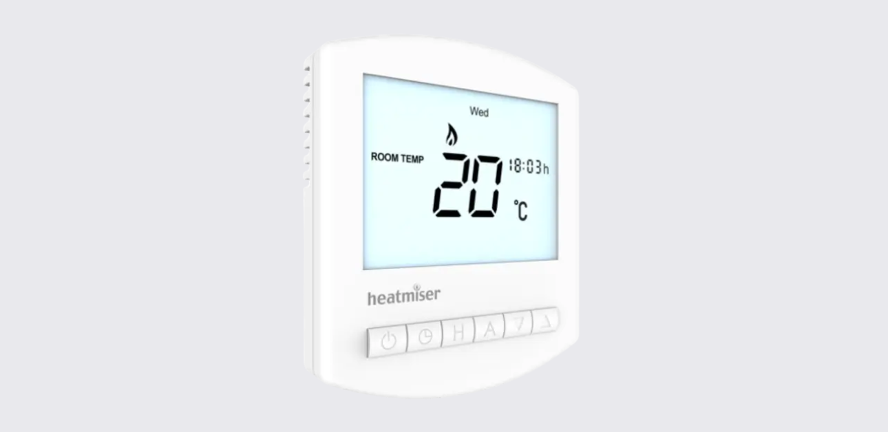
Mode 1: Thermostat Mode
Thermostat LCD Display
| Display Item | Meaning |
| Room/Floor Temp | Shows the current sensor mode |
| Day indicator | Displays the current day |
| Frost icon | Shows frost protection mode |
| Flame icon | Shows heating demand; flashes during optimum start |
| Floor temp limit icon | Shows the floor probe has reached the set limit |
| Set | Appears when changing programs or set points |
| Holiday indicator | Shows holiday mode |
| Current temperature | Displays current sensor temperature |
| Program cycle indicator | Shows Wake, Leave, Return, or Sleep during programming |
| Keypad lock | Shows the keypad is locked |
| Temperature unit | Shows °C or °F |
| Clock | Shows time in 24-hour format |
| Hold For | Shows active temperature hold and remaining time |
Setting the Clock in Programmable Mode
- Turn the thermostat on.
- Press the Clock key twice.
- Use Up/Down to set the hour.
- Press H to confirm.
- Use Up/Down to set the minutes.
- Press H to confirm.
- Use Up/Down to set the day of the week.
- Press A to save and return to the main display.
The manual notes that when Feature 11 is set to Manual Mode, the clock button does not respond.
Temperature Display and Sensor Options
The Slimline V4 can be set up to use:
- Air sensor
- Floor sensor
- Air and floor sensor together
- Remote air sensor
- Remote air and floor sensor together
The display shows either Room Temp or Floor Temp to show which sensor is being controlled. When both sensors are used, room temperature is shown by default. To view floor temperature, press and hold the A key until the floor temperature appears.
Comfort Levels and Programming
The Slimline V4 supports three programming modes:
| Program Mode | Description |
| 5/2 Day Programming | Four levels for weekdays and four different levels for weekends |
| 7 Day Programming | Four levels for each day |
| 24 Hour Programming | Four levels for all days |
Comfort Levels
The four comfort periods are:
- Wake
- Leave
- Return
- Sleep
How to Program Comfort Levels
- Press the Clock key once.
- Use Up/Down to enter the required Wake time.
- Press H to confirm.
- Use Up/Down to enter the Wake temperature.
- Press H to confirm.
- Repeat the steps for Leave, Return, and Sleep.
- For unused periods, enter –.–.
- Press A to confirm and return to the main display.
In 7-day mode, each day can be programmed independently. In 5/2 day mode, weekdays and weekends can have separate schedules.
Locking the Thermostat
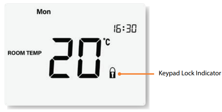
The Slimline V4 includes a keypad lock.
Lock or Unlock the Thermostat
- Press and hold A + Down together for 10 seconds.
- The lock symbol appears when the keypad is locked.
- Repeat the same step until the lock symbol disappears to unlock it.
Temperature Control
To adjust the set temperature:
- Press Up or Down.
- The display shows SET and the desired temperature.
- Use Up/Down to change the set value.
- Press A to confirm.
In programmable mode, this temperature override stays active only until the next programmed comfort level. In non-programmable mode, the thermostat maintains the selected temperature constantly.
Temperature Hold
Temperature Hold lets users override the program for a selected time and temperature.
Set Temperature Hold
- Press H.
- Use Up/Down to enter the required hold time.
- Press H to confirm.
- Use Up/Down to enter the hold temperature.
- Press A to confirm.
The screen shows Hold For and counts down the remaining time. When the timer ends, the thermostat returns to the normal program.
Cancel Temperature Hold
Repeat the same steps and reduce the hold time to 00:00.
Holiday Mode
Holiday mode reduces the set temperature to the frost protection temperature while users are away.
How Holiday Mode Works
- The thermostat maintains the frost temperature during the holiday period.
- It returns to the programmed schedule when the holiday ends.
- The holiday period starts at 00:00 the next day.
Example: if a 2-day holiday is set on Friday, Saturday is counted as the first day, and the thermostat returns to the programmed schedule at 00:00 on Monday.
Set Holiday Mode
- Press H three times until the suitcase icon appears.
- Use Up/Down to enter the number of holiday days.
- Press A to confirm.
To cancel Holiday Mode, repeat the steps and reduce the duration to 00 days.
Frost Protection
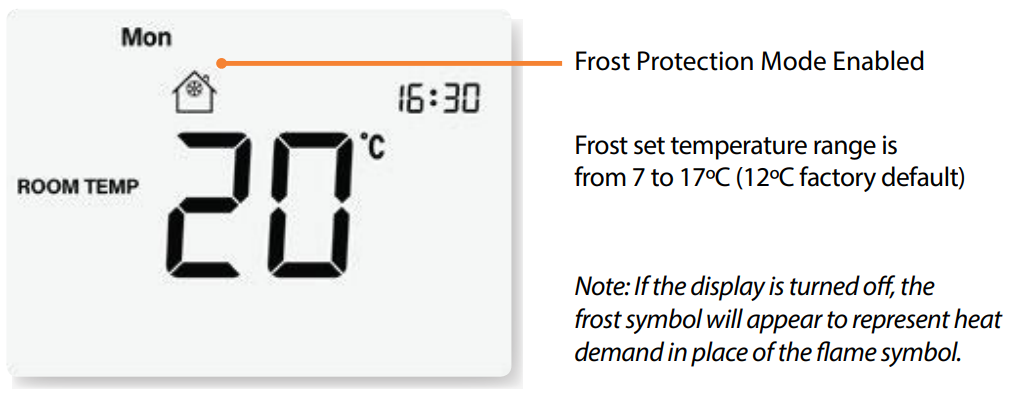
Pressing the Power button once places the thermostat into frost protection mode.
In Frost Protection Mode:
- The frost icon appears.
- Heating turns on only if the room temperature drops below the frost set temperature.
- The flame icon appears if heating activates.
- Pressing the Power button again cancels frost mode.
The frost temperature range is 7°C to 17°C, with 12°C as the factory default.
Heating On and Off
The heating is active when the flame icon appears. If the flame icon is absent, there is no heating demand, but the thermostat remains active.
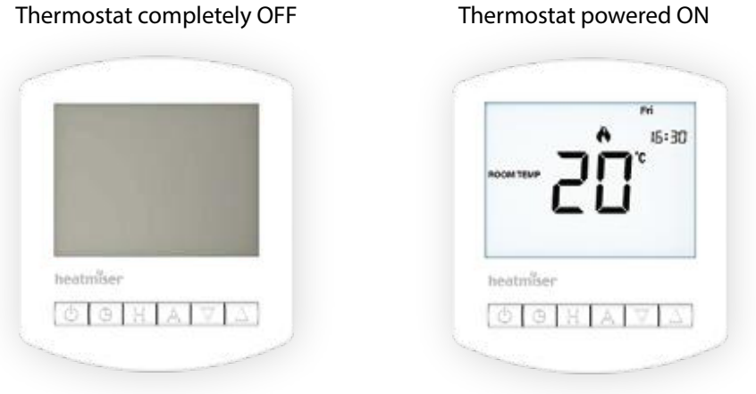
Turn the Thermostat Off Completely
Press and hold the Power button.
The display and heating output turn off completely.
Turn It Back On
Press the Power button once.
Optional Thermostat Features
| Feature | Description | Settings |
| 01 | Temperature format | 00 = °C, 01 = °F |
| 02 | Switching differential | 1°C to 3°C |
| 03 | Frost mode | 00 = enabled, 01 = disabled |
| 04 | Output delay | 00 to 15 minutes |
| 05 | Up/down temperature limit | 00°C to 10°C |
| 06 | Sensor selection | Built-in air, remote air, floor, built-in + floor, remote air + floor |
| 07 | Floor temperature limit | 20°C to 45°C |
| 08 | Optimum start | 00 to 03 hours |
| 09 | Rate of change | Minutes to raise temperature by 1°C |
| 10 | Program mode | 5/2 day, 7 day, 24-hour |
| 11 | Thermostat mode | Manual or programmable |
Adjusting Optional Features
- Press and hold the Power button to turn the thermostat off.
- Press and hold the Clock key until the optional feature screen appears.
- Use the Clock key to move through features.
- Use Up/Down to change the setting.
- Press A to confirm.
- Press the Power button once to turn the thermostat back on.
Re-Calibrating the Thermostat
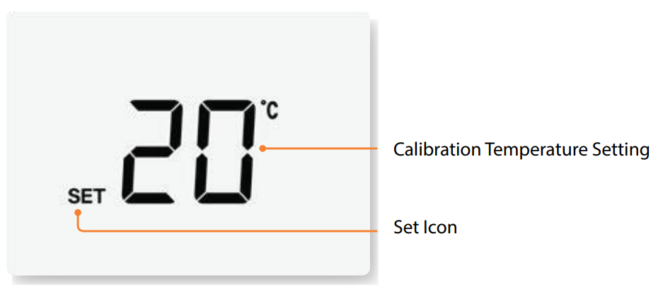
- Press and hold the Power button to turn the thermostat off.
- Press and hold Power + Down together until the temperature appears.
- Use Up/Down to set the new calibration temperature.
- Press A to confirm.
- Press Power once to turn the thermostat back on.
Error Codes
| Error Code | Meaning | Recommended Action |
| E0 | Internal sensor fault | Contact the thermostat retailer |
| E1 | Remote floor probe not connected, wired incorrectly, or faulty | Check floor probe wiring or replace the probe |
| E2 | Remote air probe not connected, wired incorrectly, or faulty | Check remote air probe wiring or replace the probe |
Mode 2: Time Clock Mode
Time Clock Overview
The Slimline V4 can also work as a time clock to control devices around the home, such as:
- Hot water
- Towel rails
- Lighting
The manual advises users to refer to the manufacturer’s instructions when wiring to these devices.
Time Clock LCD Display
| Display Item | Meaning |
| Day indicator | Shows current day |
| Holiday indicator | Shows holiday mode |
| Set | Appears when changing programs or clock settings |
| Program cycle indicators | Shows which switching period is being edited |
| Keypad lock | Shows keypad lock is active |
| Timer status | Shows current timed output status |
| Clock | Shows time in 24-hour format |
| Hold For | Shows active timer override and remaining time |
Setting the Clock in Time Clock Mode
- In Countdown Mode, press the Clock button once.
- In 5/2, 7-day, or 24-hour mode, press the Clock button twice.
- Use Up/Down to set the hour.
- Press H to confirm.
- Use Up/Down to set the minutes.
- Press H to confirm.
- Use Up/Down to set the day of the week.
- Press A to confirm and return to the main display.
Locking the Time Clock
- Press and hold A + Down together for 10 seconds.
- The lock symbol appears.
- Repeat the same step until the lock symbol disappears to unlock it.
Setting the Switching Times
- Press the Clock button once.
- Use Up/Down to select the Timer ON time for the Wake switching period.
- Press H to confirm.
- Use Up/Down to select the Timer OFF time.
- Press H to confirm.
- Repeat the steps for Leave, Return, and Sleep periods.
- Set unused periods to –:–.
- In 5/2 day mode, repeat the process for the weekend.
- Press A to confirm and return to the main display.
Countdown Mode
Countdown Mode turns the output on for a selected duration.
Use Countdown Mode
- Use Up/Down to set the countdown duration.
- Press A to confirm.
- Hold For appears and shows the remaining time.
- The output remains active while Hold For is displayed.
To cancel countdown, reduce the time to 00:00.
Timer Override
The time clock can override its current timer status.
If the current status is Timer ON, pressing A switches it to Timer OFF. The timer status flashes to show that the programmed output has been overridden. The time clock returns to the program at the next scheduled switching time.
Holiday Mode in Time Clock
Holiday Mode keeps the time clock output OFF while the user is away.
Set Holiday Mode
- Press H once until the suitcase appears.
- Use Up/Down to enter the number of holiday days.
- Press A to confirm.
Holiday mode starts at 00:00 the next day and returns to the normal schedule when the selected holiday period ends.
Optional Time Clock Features
| Feature | Description | Settings |
| 01 | Programming mode | 00 = 5/2 day, 01 = 7 day, 02 = 24-hour |
| 02 | Time clock mode | 00 = Countdown, 01 = Programmable |
Wiring Diagram
The manual includes wiring diagrams for multiple heating setups.
| Wiring Diagram | Purpose |
| Slimline to Boiler 230V | Switched live boiler connection |
| Slimline to Boiler Voltfree | Volt-free boiler thermostat connection |
| Slimline to Spring Return Valve | Heating valve and boiler connection |
The diagrams include terminals such as RT2, RT1, -, A2, A1, N, and L. The manual also notes that the unit must be protected by a fuse or RCD in the volt-free and spring return valve diagrams.
Troubleshooting Guide
| Problem | Possible Cause | Recommended Action |
| Display does not turn on | Thermostat may be off or power issue | Press Power or check supply/wiring |
| Heating does not turn on | Set temperature may already be reached | Check flame icon and set temperature |
| Clock button does not respond | Thermostat is in manual mode | Check Feature 11 |
| Buttons do not respond | Keypad lock is active | Hold A + Down for 10 seconds |
| Floor limit icon appears | Floor sensor reached limit | Check Feature 07 floor temperature limit |
| E0 appears | Internal sensor fault | Contact thermostat retailer |
| E1 appears | Floor probe issue | Check floor probe wiring |
| E2 appears | Remote air probe issue | Check remote air probe wiring |
| Temperature seems inaccurate | Calibration may be needed | Use recalibration steps carefully |
| Time clock output stays off | Holiday mode or Timer OFF override active | Check holiday mode and timer status |
| Countdown does not cancel | Countdown duration still active | Reduce countdown time to 00:00 |
| Boiler does not respond | Wiring issue or wrong diagram used | Have a qualified electrician check wiring |
Heatmiser UK Ltd Support
Heatmiser provides technical support, PDFs, FAQs, videos, and product specifications through its official channels.
Phone: +44 (0)1254 669090
Website: www.heatmiser.com
Twitter/X: @heatmiseruk
Facebook: facebook.com/thermostatsAddress:
Heatmiser UK Ltd
Units 1–5 Hurstwood Court, Mercer Way
Shadsworth Business Park
Blackburn, Lancashire, BB1 2QU
United Kingdom