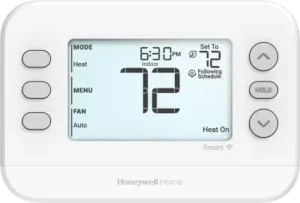
| Field | Details |
| Document Title | FocusPRO P200 & S200 Series Thermostats Installation Manual |
| Document Type | Installation Manual |
| Brand Name | Honeywell Home |
| Product Name | FocusPRO P200 & S200 Series Thermostats |
| Model Numbers | TH2110U4004, TH2320U4006, TH2110WF4008, TH2320WF4010, TH2320WF4011 |
| PDF File Size | 1.66 MB |
| Total Number of Pages | 89 |
| Languages Covered | English, French, Spanish |
Honeywell Home FocusPRO P200 & S200 Series Thermostats
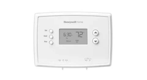
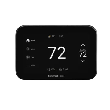
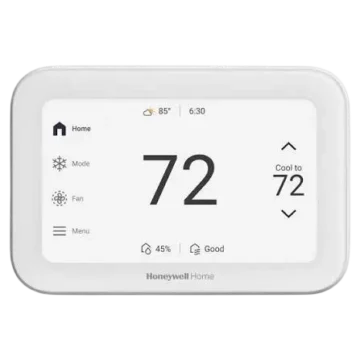
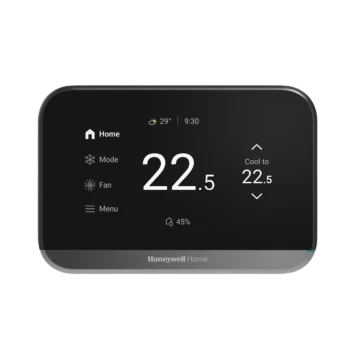
The Honeywell Home FocusPRO P200 and S200 Series Thermostats provide programmable heating and cooling control for compatible 24 VAC systems. The series includes the P200 programmable thermostats and the S200 smart thermostats, which support WiFi connectivity and app-based setup.
These thermostats are designed for indoor use with supported conventional heating and cooling systems, heat pumps, and selected hydronic heating equipment. The TH2110 models support single-stage systems, while the TH2320 models provide additional support for multistage heating and cooling, auxiliary heat, and dual-fuel configurations.
The installation and configuration instructions apply to the following models:
| Model Number | Series | Thermostat Type |
| TH2110U4004 | P200 | Programmable thermostat |
| TH2320U4006 | P200 | Programmable thermostat |
| TH2110WF4008 | S200 | Smart thermostat |
| TH2320WF4010 | S200 | Smart thermostat |
| TH2320WF4011 | S200 | Smart thermostat |
Installation must be completed with power disconnected and with the thermostat configured for the connected heating and cooling equipment.
What’s Included in the Box
The FocusPRO P200 and S200 thermostat packages contain the components required for standard wall mounting and installation.
| Included Component | Description |
| FocusPRO Thermostat | P200 programmable thermostat or S200 smart thermostat, depending on the model purchased |
| UWP Wall Plate | Wall mounting base with electrical wiring terminals |
| Decorative Cover Plate with J-Box Adapter | Covers the mounting area and supports installation with a junction box |
| Screws and Anchors | Hardware for securing the wall plate |
| 2 AA Batteries | Included with P200 models only |
| Thermostat Literature | Product documentation and installation instructions |
Safety Instructions and Precautions
Electrical Shock and Equipment Damage Warning
CAUTION: Electrical hazard.
Installation involves electrical connections that can cause electric shock or damage to the equipment.
Power must be disconnected at the circuit breaker or system switch before beginning installation.
Compressor Protection Warning
CAUTION: Equipment damage hazard.
The thermostat’s compressor protection feature is bypassed during installer testing. Rapidly cycling the compressor during testing can damage the heating or cooling equipment.
Avoid switching the compressor on and off repeatedly during the installer test.
Mercury Disposal Warning
If the thermostat replaces an older control containing mercury inside a sealed glass tube, the old control must not be discarded in household trash.
Contact the local waste management authority for appropriate recycling and disposal instructions.
Electronic Waste Disposal
The thermostat and its batteries must not be discarded with ordinary household waste.
Use an authorized recycling facility or collection center for disposal of electronic equipment and batteries.
Heating and Cooling System Compatibility
The FocusPRO P200 and S200 thermostats are intended for indoor installation with compatible 24 VAC heating and cooling equipment.
Compatibility varies between TH2110 and TH2320 models.
TH2110U4004 and TH2110WF4008 Compatibility
These models support single-stage heating and cooling configurations, including:
- Heat pumps without auxiliary heating.
- Gas, oil, and electric forced-air heating.
- Single-stage cooling systems.
- Radiant hydronic heating.
- Hot water coil heating.
- Supported 750 mV heating applications.
For 750 mV applications using the S200 smart thermostat, a separate 24 VAC supply is required at the Rc and C terminals. The 750 mV circuit connects to R and W according to the applicable wiring configuration.
TH2320U4006, TH2320WF4010, and TH2320WF4011 Compatibility
The TH2320 models support a broader range of heating and cooling equipment, including:
- Heat pumps with one or two compressor stages and auxiliary heating.
- Dual-fuel heating systems.
- Single-stage and two-stage gas, oil, or electric forced-air heating.
- Single-stage and two-stage cooling.
- Radiant hydronic heating and hot water coils.
- Supported 750 mV heating applications.
- C7089U1006 wired outdoor temperature sensors.
The wired outdoor sensor can be used for heat-pump balance point settings or auxiliary heat lockout. On applicable smart models, outdoor temperature information can also be obtained through the app.
Model Compatibility Comparison
| Feature | TH2110 Models | TH2320 Models |
| Single-stage heating | Supported | Supported |
| Single-stage cooling | Supported | Supported |
| Heat pump without auxiliary heat | Supported | Supported |
| Multistage conventional heating | — | Supported |
| Two-stage cooling | — | Supported |
| Two-stage compressor operation | — | Supported |
| Auxiliary heating | — | Supported |
| Dual-fuel systems | — | Supported |
| Wired C7089U1006 outdoor sensor | — | Supported |
| WiFi | S200 model only | S200 models only |
The S200 smart models support 2.4 GHz and 5 GHz WiFi networks.
Thermostat Parts and Components
The thermostat installation system consists of the thermostat unit, the UWP mounting plate, wiring terminals, and optional decorative mounting components.
UWP Wall Plate
The UWP wall plate serves as the mounting base and electrical connection point.
It includes:
- Electrical terminal connections.
- Wire insertion openings.
- Terminal release tabs.
- R/Rc slider tab.
- Mounting screw positions.
- A wiring access door.
- Connection points for the thermostat body.
Decorative Cover Plate and Mounting Plate
The optional decorative cover plate is intended to conceal gaps or unpainted areas left by a previous thermostat.
Its mounting plate can be attached directly to the wall or to a junction box.
Thermostat Buttons and Display
The thermostat includes dedicated buttons for operating mode selection, fan control, menus, temperature adjustments, and on-screen selections.
| Button or Control | Function |
| MODE | Cycles between available heating and cooling operating modes |
| FAN | Selects the available fan operating modes |
| MENU | Opens thermostat settings and user menu options |
| Up Arrow | Increases a setpoint or changes a menu selection |
| Down Arrow | Decreases a setpoint or changes a menu selection |
| SELECT | Confirms the current menu selection |
| NEXT | Advances to the next setup or programming step |
| SAVE & EXIT | Saves settings and returns to the home screen |
| HOLD | Controls temporary and permanent schedule overrides |
| EXIT | Leaves the current menu |
| UNLOCK | Opens the keypad unlocking procedure when the thermostat is locked |
Some button labels change depending on the current menu or function.
Power Requirements and Power Options
The thermostats use a nominal 24 VAC power supply.
The P200 models also support AA battery power, while the S200 smart thermostats require a common-wire connection for their power supply.
S200 Smart Thermostat Power Requirements
The S200 thermostat requires appropriate R/Rc and C connections to receive operating power.
The C terminal is required for S200 smart thermostats.
The AC power wires must be placed in their designated terminals on the UWP wall plate.
To remove a wire, the corresponding terminal tab is pressed to release the connection.
Using the THP9045A C-Wire Adapter
The THP9045A C-wire adapter can be used with eligible installations where a common wire is unavailable.
The adapter is applicable to thermostats using Y and G wires when:
- The previous thermostat did not have a C-wire connection.
- No additional wire is available in the thermostat wiring bundle.
The THP9045A adapter is sold separately.
P200 Battery Power
The P200 programmable models can use two AA batteries for primary or backup power.
Battery installation and replacement apply only to the P200 models.
UWP Wall Plate Installation
The UWP wall plate must be secured to the wall before the thermostat is mounted.
How to Install the UWP Wall Plate
- Turn off the power at the circuit breaker or system switch.
- Locate the UWP wall plate in the thermostat package.
- Position the UWP against the wall in the required location.
- Level the wall plate and mark the mounting hole positions.
- Drill holes at the marked positions using a 3/16-inch drill bit.
- Gently tap the supplied wall anchors into the drilled holes using a hammer.
- Open the UWP wiring access door.
- Pass the thermostat wires through the opening in the wall plate.
- Position the UWP over the installed wall anchors.
- Insert the supplied mounting screws.
- Tighten the screws until the UWP is firmly secured and no longer moves.
- Close the access door.
Use the three supplied #6 × 1-1/2-inch screws.
Important: Do not overtighten the mounting screws.
Optional Decorative Cover Plate Installation
The decorative cover plate can be installed when an older thermostat has left a visible paint gap or uncovered wall area.
- Separate the decorative cover plate from its mounting plate.
- Position the mounting plate against the wall or junction box.
- Select the appropriate mounting holes from the eight available screw positions.
- Attach the mounting plate using the screws provided with the cover plate kit.
- Keep the mounting plate level while tightening the screws.
- Do not overtighten.
- Place the UWP onto the upper hook of the mounting plate.
- Press the lower section of the UWP until it snaps into position.
- Snap the decorative cover plate onto the mounting plate.
Wiring Terminals and Connections
The UWP includes terminals for heating, cooling, fan control, heat-pump operation, and power connections.
Not every terminal is used on every model or system configuration.
Wiring Terminal Designations
| Terminal | Function |
| S / S | C7089U1006 wired outdoor temperature sensor connection; TH2320 models only |
| Y | First-stage compressor contactor |
| Y2 | Second-stage compressor contactor; TH2320 models only |
| G | Fan control |
| C | 24 VAC common connection |
| U / U | Not used on FocusPRO P200 and S200 models |
| L/A | Heat-pump fault input |
| O/B | Heat-pump changeover valve |
| AUX/W2 | Auxiliary heating or second-stage heating; TH2320 models only |
| E | Emergency heat; TH2320 models only |
| W | First-stage heating |
| K | THP9045A C-wire adapter connection |
| R | 24 VAC power from the heating transformer |
| Rc | 24 VAC power from the cooling transformer |
For a two-transformer system, the C terminal uses the common wire from the cooling transformer.
Setting the R/Rc Slider Tab
The UWP wall plate includes an R/Rc slider tab that serves as a built-in jumper for single-transformer installations.
The required position depends on the number of R connections.
| Wiring Configuration | Slider Position |
| One R wire connected to R, Rc, or RH | Up position — 1 wire |
| Separate wires connected to R and Rc | Down position — 2 wires |
The slider tabs associated with the U terminals must remain in place for FocusPRO P200 and S200 models.
Wiring Diagrams for Different HVAC Systems
The appropriate wiring configuration depends on the thermostat model and the connected heating or cooling equipment.
Conventional Heating and Cooling Systems
The installation manual provides wiring diagrams for:
| HVAC Configuration | Compatible Models |
| Heat-only gas or oil furnace | All P200 and S200 models |
| Cooling-only system | All P200 and S200 models |
| Hot water boiler, heat only | All P200 and S200 models |
| 1H/1C gas furnace | All P200 and S200 models |
| Two-transformer 1H/1C oil furnace with air conditioning | All P200 and S200 models |
| Two-transformer hot water heating with air conditioning or hot water coil | All P200 and S200 models |
| 2H/1C gas furnace | TH2320 models only |
| 2H/2C gas furnace | TH2320 models only |
For heat-only gas or oil forced-air systems, the G terminal is used only when independent fan control is required. Most heat-only gas or oil forced-air installations do not use the G connection.
Hydronic Heating and Zone Valve Systems
The thermostat supports the following documented hydronic configurations:
- Hot water heating with a power-open zone valve.
- Hot water heating with a Series 20 power-open/power-closed zone valve.
For the Series 20 zone valve configuration, the thermostat must be configured for radiant heating with zero cooling stages.
Heat Pump Wiring Configurations
| Heat Pump Configuration | Compatible Models |
| 1H/1C heat pump without auxiliary heat | All P200 and S200 models |
| 2H/1C heat pump with electric auxiliary heat | TH2320 models only |
| 3H/2C heat pump with electric auxiliary heat | TH2320 models only |
| Dual-fuel 2H/1C heat pump | TH2320 models only |
| Dual-fuel 3H/2C heat pump | TH2320 models only |
Important Heat Pump Wiring Instructions
The following wiring conditions must be observed:
- The L connection is used only when the heat pump has a fault terminal.
- Some heat pumps use a B connection instead of O for the reversing valve.
- Auxiliary heating terminals may be labeled differently between heat pump manufacturers.
- The C7089U1006 wired outdoor sensor can be used for balance point and auxiliary heat lockout functions where supported.
- Most heat pumps share the same heating strips for auxiliary and emergency heating. In these configurations, a separate E connection is not used.
- TH2320 models can be configured for independent auxiliary and emergency heating connections when the equipment supports separate heating elements.
Important: The heat-pump wiring diagrams warn against connecting a heat-pump wire to the W terminal, because this can cause continuous heating. Dual-fuel diagrams distinguish the furnace W connection from the heat-pump connections.
Electrical connections must follow the diagram for the actual HVAC equipment and thermostat model.
Mounting the Thermostat
After the required wiring and UWP installation have been completed, the thermostat can be attached to the wall plate.
How to Attach the Thermostat
- Push any excess thermostat wire back into the wall opening.
- Close the UWP access door.
- Check that the door closes completely without bulging.
- Align the thermostat with the mounted UWP.
- Press the thermostat gently toward the wall plate until it snaps securely into place.
- Turn the power back on using the circuit breaker or system switch.
The thermostat can then proceed to its initial configuration.
Initial Thermostat Configuration
The thermostat must be configured to match the installed heating and cooling system.
The P200 models provide on-device configuration. The S200 smart models can be configured directly on the thermostat or through the Resideo Pro app.
Configuring an S200 Smart Thermostat
During initial configuration, the S200 provides two setup methods:
- Using App: Configuration through the Resideo Pro app.
- On Device: Configuration using the thermostat buttons and Installer Setup menu.
When Using App is selected, the Resideo Pro app provides the setup instructions.
When On Device is selected, the thermostat’s Installer Setup options are used to configure the connected equipment.
How to Access the Installer Menu
After initial setup, the Installer Menu can be accessed using a button combination.
- Press and hold the bottom-left button and the Up Arrow simultaneously.
- Continue holding both buttons for five seconds.
- The display opens the INSTALLER MENU.
- Press the Up or Down Arrow to move through the available options.
- Press SELECT when the required option appears.
Installer Menu Options
| Menu Option | Function |
| ISU | Installer Setup settings for configuring the thermostat and HVAC equipment |
| TEST | Installer testing of heating, cooling, emergency heat, and fan operation |
| INFO | Displays information used by Resideo technical support |
| RSET | Provides schedule reset, S200 WiFi reset, and factory reset options |
| REV | Displays thermostat firmware version and WiFi version information |
To return to the home screen, press EXIT in the upper-left position or allow the menu to time out.
How to Configure Installer Setup Options
- Open the Installer Menu.
- Navigate to ISU.
- Press SELECT.
- The display shows the ISU number on the left and its selected value on the right.
- Use the Up or Down Arrow to change the selected ISU setting.
- Press NEXT to move to the next installer setting.
- Continue configuring the required settings.
- Press SAVE & EXIT after completing the configuration.
The thermostat saves the selected settings and returns to the home screen.
Installer Setup Options (ISU)
Installer Setup options control HVAC system type, equipment staging, temperature limits, scheduling, fan operation, display behavior, and other configuration features.
Available options depend on the model and the configured system.
Scheduling, Temperature, and Equipment Settings
| ISU Number | Setting | Available Options |
| 1040 | Scheduling Options | 1-week, 5-2, 5-1-1, or 7-day programming |
| 1050 | Temperature Display Scale | Fahrenheit or Celsius |
| 1060 | Outdoor Sensor | None, wired outdoor sensor, or internet weather where supported |
| 2000 | Heating System Type | Conventional forced air, heat pump, radiant heat, or none for cooling-only systems |
| 2010 | Heating Equipment Type | Gas, oil, electric forced air, hot water fan coil, air-to-air heat pump, geothermal heat pump, hot water radiant heat, or steam |
| 2060 | Reversing Valve O/B | O energized for cooling or B energized for heating |
| 2070 | Compressor Stages | 0, 1, or 2, depending on model |
| 2071 | Heating and Backup Heat Stages | Heating stages 1 or 2; backup heat stages 0 or 1 on TH2320 models |
| 2110 | Fan Control in Heat | Equipment-controlled or thermostat-controlled |
| 2175 | AUX/E Terminal Control | AUX and E operated together or independently |
| 2180 | Backup Heat Source | Equipment-specific backup heating source selection |
| 2185 | Emergency Heat Source | Equipment-specific emergency heating source selection |
For ISU 1040, the scheduling options operate as follows:
- 1-week: The same schedule applies every day.
- 5-2: Weekdays and weekends have separate schedules.
- 5-1-1: Weekdays, Saturday, and Sunday can have separate schedules.
- 7-day: Every day can have an individual schedule.
For ISU 1060, wired outdoor sensing applies to TH2320 models. Internet weather is available on applicable TH2320WF smart thermostats.
ISU 2070 permits only one compressor stage on TH2110 models.
ISU 2110 appears when the selected equipment type is electric forced air or a hot water fan coil.
Heating Equipment Type Codes
ISU 2010 uses the following equipment selections.
| Code | Equipment Type |
| 1 | Standard-efficiency gas forced air |
| 2 | High-efficiency gas forced air |
| 3 | Oil forced air |
| 4 | Electric forced air |
| 5 | Hot water fan coil |
| 7 | Air-to-air heat pump |
| 8 | Geothermal heat pump |
| 9 | Hot water radiant heat |
| 12 | Steam |
Reversing Valve Settings
ISU 2060 determines whether the heat-pump reversing valve is energized during heating or cooling.
- 0 — O: The O/B terminal operates the reversing valve during cooling.
- 1 — B: The O/B terminal operates the reversing valve during heating.
The selection must correspond to the requirements of the connected heat pump.
Backup and Emergency Heat Source Codes
The installer options include the following source types for supported TH2320 configurations.
| Code | Heating Source |
| 31 | Electric forced air |
| 32 | Standard-efficiency gas forced air |
| 33 | High-efficiency gas forced air |
| 34 | Oil forced air or hot water fan coil |
| 35 | Hot water radiant heat |
| 36 | Other |
Automatic Changeover and Advanced Heating Settings
| ISU Number | Setting | Available Values or Function |
| 3000 | System Changeover | Manual only or automatic changeover enabled |
| 3015 | Auto Changeover Differential | 0°F–5°F (0.0°C–2.5°C) |
| 3020 | Finish With High Heat Stage | No or Yes; TH2320 models only |
| 3021 | Finish With High Cool Stage | No or Yes; TH2320 models only |
| 3090 | Backup Heat Droop | Comfort setting or 2°F–15°F (1.0°C–7.5°C) |
| 3110 | Upstage Timer for Backup Heat | Off or selectable delays from 30 minutes to 16 hours |
| 3120 | Compressor Lockout / Balance Point | Off or −15°F to 60°F in 5°F increments |
| 3121 | Outdoor Lockout Backup Heat | Off or 5°F–65°F in 5°F increments |
| 3125 | Lockout Fan After a Cool Call | Off or 5–120 minutes in five-minute increments |
Automatic changeover is not recommended when outdoor temperatures frequently remain below 50°F (10°C) during winter.
The ISU 3090 Comfort setting is available only when the backup heat source is configured as electric.
For ISU 3110, the available timer selections depend on the backup heating configuration. When ISU 3090 is set to Comfort and ISU 2180 is set to electric heat, only Off, 30 minutes, 45 minutes, and 60 minutes are available.
ISU 3120 requires outdoor temperature information to be configured through a wired sensor or internet weather.
Equipment Cycle Rate and Compressor Protection
| ISU Number | Setting | Available Options |
| 3140 | Compressor Cycle Rate, Stage 1 | 1–6 |
| 3141 | Compressor Cycle Rate, Stage 2 | 1–6; TH2320 models only |
| 3150 | Heating Cycle Rate, Stage 1 | 1–12 |
| 3151 | Heating Cycle Rate, Stage 2 | 1–12; TH2320 models only |
| 3160 | Auxiliary Heating Cycle Rate | 1–12; TH2320 models only |
| 3165 | Emergency Heating Cycle Rate | 1–12; TH2320 models only |
| 3240 | Compressor Protection | Off or 1–5 minutes |
| 4090 | Adaptive Intelligent Recovery | No or Yes |
The compressor protection setting determines the delay that can occur before the compressor is permitted to restart.
Temperature Setpoint Limits and Keypad Lockout
| ISU Number | Setting | Configuration Range |
| 4100 | Maximum Cool Setpoint | 50°F–99°F (10°C–37°C) |
| 4101 | Minimum Cool Setpoint | 50°F–99°F (10°C–37°C) |
| 4102 | Maximum Heat Setpoint | 32°F–90°F (0°C–32°C) |
| 4103 | Minimum Heat Setpoint | 32°F–90°F (0°C–32°C) |
| 4110 | Keypad Lockout | Disabled or Enabled |
The documented factory maximum heating setpoint is 90°F, while the default minimum heating setpoint is 40°F. Installer settings can change the permitted range within the specified limits.
Air Filter Reminder Settings
The thermostat supports configurable reminders for up to two air filters.
| ISU Number | Setting | Options |
| 7020 | Number of Air Filters | 0, 1, or 2 |
| 7110 | Air Filter 1 Replacement Reminder | Off or selected runtime/calendar intervals |
| 7111 | Air Filter 2 Replacement Reminder | Off or selected runtime/calendar intervals |
Available runtime-based reminder intervals are 10, 20, 30, 45, 60, 90, 120, and 150 days.
Calendar-based intervals include 30, 45, 60, or 75 days, and 3, 4, 5, 6, 9, 12, or 15 months.
Display, Backlight, and Clock Settings
| ISU Number | Setting | Available Options |
| 14003 | Backlighting | On Demand or Continuous |
| 14004 | Backlight Brightness | Levels 1–5 |
| 14005 | Idle Screen Selection | Minimum information, setpoint, or maximum information |
| 14006 | Idle Screen Message Center | Time, outdoor temperature, outdoor humidity, or indoor humidity where supported |
| 14007 | Home Screen Message Center | Time, outdoor temperature, outdoor humidity, or indoor humidity where supported |
| 14010 | Clock Format | 12-hour or 24-hour |
| 14015 | Daylight Saving Time | Off or On |
| 14020 | Temperature Display Offset | −3°F to +3°F (−1.5°C to +1.5°C) |
Continuous backlighting requires a common-wire connection.
Backlight brightness adjustment is available when continuous backlighting is selected.
Outdoor temperature display requires a compatible outdoor sensor or internet weather configuration. Outdoor humidity requires the supported internet weather configuration.
Installer System Test
The Installer Test menu allows the connected heating, cooling, emergency heating, and fan equipment to be tested.
Caution: Compressor protection is bypassed during testing. Avoid rapid compressor cycling.
How to Run an Installer Test
- Press and hold the bottom-left button and the Up Arrow for five seconds.
- The Installer Menu opens.
- Navigate to TEST.
- Press SELECT.
- The display shows the current test mode.
- Press the Up Arrow to activate the displayed test.
- On multistage equipment, pressing the Up Arrow again can request the next equipment stage.
- Press NEXT to move to another test mode.
- Press EXIT when testing is complete.
Installer Test Modes and Status Numbers
| Test Mode | Status Number | Meaning |
| Heat | 0 | All heating stages off |
| Heat | 1 | Heating stage 1 on |
| Heat | 2 | Heating stage 2 also on |
| Heat | 3 | Heating stage 3 also on |
| Cool | 0 | Cooling off |
| Cool | 1 | Cooling stage 1 on |
| Cool | 2 | Cooling stage 2 also on |
| Emergency Heat | 0 | Emergency heating off |
| Emergency Heat | 1 | Emergency heating on |
| Fan | 0 | Fan off |
| Fan | 1 | Fan on |
Additional heating and cooling stages and emergency heat testing apply to supported TH2320 configurations.
User Menu and Thermostat Settings
After the thermostat has been configured, the User Menu provides access to scheduling, wireless settings, temperature information, time, date, and keypad controls.
How to Open the User Menu
- Press MENU.
- Use the Up or Down Arrow to move through the available options.
- Press SELECT when the required setting appears.
- To return to the home screen, press EXIT or allow the thermostat menu to time out.
Available User Menu Options
| Menu Option | Function |
| SCHEDULE | Enable, disable, or edit temperature schedules |
| APP | Access the app option on S200 models |
| WIFI | Turn WiFi on or off on S200 models |
| TEMP | View indoor or available outdoor temperature information |
| DATE | Set the calendar date |
| TIME | Set the clock |
| LOCK | Select keypad lockout settings when enabled by the installer |
When an alert or reminder is active, it appears before the other menu items.
The outdoor temperature option is available when the thermostat has been configured to use a wired outdoor sensor or internet weather.
Setting the Time and Date
The thermostat supports manual time and date settings.
When an S200 thermostat is registered to a First Alert Account, its time and date are set automatically.
How to Set the Clock
- Press MENU.
- Use the arrow buttons to find TIME.
- Press SELECT.
- Choose the 12-hour or 24-hour clock format.
- Press NEXT.
- Adjust the hour using the arrow buttons.
- Press NEXT.
- Adjust the minutes.
- Press SAVE & EXIT.
How to Set the Date
- Press MENU.
- Navigate to DATE.
- Press SELECT.
- Adjust the year.
- Press NEXT.
- Adjust the month.
- Press NEXT.
- Adjust the date.
- Press SAVE & EXIT.
System Operating Modes
The FocusPRO thermostat provides different system operating modes according to its model and HVAC configuration.
How to Change the System Mode
- Press the MODE button.
- Continue pressing MODE to cycle through the available settings.
- Stop when the required operating mode appears on the display.
Available Modes
| Mode | Description |
| HEAT | Operates the configured heating equipment |
| COOL | Operates the configured cooling equipment |
| AUTO | Automatically selects heating or cooling as required |
| EM HEAT | Emergency heating mode on compatible equipment |
| OFF | Turns off normal heating and cooling operation |
Available system modes depend on the installed equipment and installer configuration.
Adjusting the Temperature
The Up and Down Arrow buttons adjust the selected temperature setpoint.
When the arrow buttons are pressed, the screen displays the relevant system mode, setpoint, and indoor room temperature.
The thermostat uses the new setpoint to determine heating or cooling demand.
Fan Operation Settings
The thermostat supports up to three fan modes.
Available Fan Modes
| Fan Mode | Operation |
| AUTO | Fan runs when the heating or cooling system operates |
| ON | Fan runs continuously |
| CIRC | Fan operates for approximately 33% of the time to circulate air |
How to Change the Fan Mode
- Press FAN.
- Continue pressing the button to move through the available fan modes.
- Stop when the required fan setting appears.
Available fan modes vary according to system configuration.
Automatic Heating and Cooling Changeover
When Auto Changeover is enabled, the thermostat maintains separate heating and cooling setpoints.
The system can switch between heating and cooling as indoor conditions change.
How to Enable Auto Changeover
- Press MODE until AUTO appears.
- Press SAVE.
- The thermostat enters the automatic changeover operating mode.
How to Adjust Auto Mode Temperature Settings
- Make sure the thermostat is in AUTO mode.
- Press the Up or Down Arrow.
- The display shows HEAT TO or COOL TO with the selected setpoint flashing.
- Use the arrow buttons to adjust the displayed temperature.
- To switch between heating and cooling setpoint adjustments, press MODE while the setpoint is flashing.
- Adjust the other temperature setting as required.
Heating and Cooling Setpoint Differential
The heating setpoint is normally placed a few degrees below the cooling setpoint.
For example, when the indoor temperature is between the selected heating and cooling temperatures, neither mode needs to operate.
The heating and cooling setpoints can also be the same temperature.
In this case, the thermostat uses an installer-configured changeover differential to prevent repeated switching between heating and cooling.
The differential determines how far the indoor temperature must change before switching from the previously active mode to the opposite mode.
Programmable Temperature Schedules
The FocusPRO thermostat supports four daily programming periods, allowing different heating and cooling temperatures to be assigned throughout the day.
Available Schedule Periods
| Schedule Period | Purpose |
| WAKE | Temperature setting for the beginning of the day |
| AWAY | Temperature setting while the building is unoccupied |
| HOME | Temperature setting for the evening or occupied period |
| SLEEP | Temperature setting for the overnight period |
Recommended Schedule Presets
The installation manual provides the following example temperature schedule.
| Period | Time | Heating | Cooling |
| WAKE | 6:00 AM | 70°F | 78°F |
| AWAY | 8:00 AM | 62°F | 85°F |
| HOME | 6:00 PM | 70°F | 78°F |
| SLEEP | 10:00 PM | 62°F | 82°F |
These values are recommended presets rather than fixed requirements.
How to Enable and Program a Schedule
- Press MENU.
- Navigate to SCHED.
- Select ON using the arrow buttons.
- Press SELECT to edit the schedule.
- The selected day or group of days flashes.
- Press SELECT to continue.
- The WAKE schedule period flashes.
- Press NEXT.
- Use the arrow buttons to enable or disable that period.
- Press NEXT.
- If the period is enabled, adjust its start time.
- Press NEXT.
- Adjust the heating setpoint.
- Press NEXT.
- Adjust the cooling setpoint.
- Press NEXT.
- Repeat the procedure for AWAY, HOME, and SLEEP.
- Continue with any remaining days or day groups.
- Press SAVE & EXIT to store the schedule.
The days available for individual editing depend on the scheduling configuration selected in Installer Setup.
Editing an Existing Schedule
To change an existing schedule:
- Open SCHED from the User Menu.
- Select the schedule for editing.
- Advance to the period and setting that requires adjustment.
- Change the selected time or temperature.
- Press SAVE & EXIT.
Disabling a Programmed Schedule
- Press MENU.
- Open SCHED.
- Select OFF instead of ON.
- Leave the menu.
Temporary and Permanent Schedule Overrides
The thermostat can temporarily or permanently override a programmed temperature schedule.
Temporary Hold
A temporary hold maintains the selected temperature until the next scheduled period begins.
- Press the Up or Down Arrow to change the temperature.
- Adjust the setpoint to the required value.
- Press SAVE or wait for the display to return to the home screen.
The thermostat maintains the temporary setting until the next programmed period.
To cancel a temporary hold, press and release HOLD until CANCEL HOLD is selected.
Permanent Hold
A permanent hold maintains the selected temperature without automatically returning to the next scheduled setting.
- Press the Up or Down Arrow to adjust the temperature.
- Press and release HOLD until the permanent hold option is displayed.
- Press SAVE or allow the display to return to the home screen.
To cancel the permanent hold, cycle the HOLD options until CANCEL HOLD is selected.
Keypad Lockout and Unlocking
The thermostat supports keypad locking when the installer has enabled this feature.
Keypad Lock Modes
| Setting | Function |
| OFF | Keypad unlocked with full access |
| PART | Partial lockout; temperature adjustment remains available |
| ON | Full lockout; access is restricted |
How to Lock the Thermostat
- Press MENU.
- Navigate to LOCK.
- Press SELECT.
- Choose OFF, PART, or ON.
- Press SELECT to confirm.
- Press SAVE & EXIT.
How to Unlock the Thermostat
When keypad locking is active, the display shows UNLOCK beside the center-left button.
- Press the center-left button labeled UNLOCK.
- The password entry display appears with a zero and three dashes.
- Use the Up or Down Arrow to set the first digit.
- Press SELECT.
- Repeat the process for the remaining digits.
- Enter the documented unlock code 1234.
- Press SELECT after entering the fourth digit.
The keypad unlocks when the correct code is accepted.
If a digit is entered incorrectly, press BACK to return to the previous entry and correct it.
The LOCK option appears in the User Menu only when the installer has enabled keypad lockout.
Smart Thermostat App and WiFi Settings
The S200 smart thermostat models include app and WiFi menu options.
WiFi Operation
The S200 models support wireless networks operating at 2.4 GHz or 5 GHz.
WiFi can be turned on or off through the thermostat’s User Menu.
App-Based Setup
The Resideo Pro app can be used for S200 installer setup.
During initial configuration, the thermostat offers an app-based setup option. When selected, configuration continues through the instructions provided in the app.
Geofencing
After an S200 thermostat is registered with the Resideo app, geofencing services can be selected as an alternative to a time-based temperature schedule.
Internet-Based Time Settings
When the thermostat is registered to a First Alert Account, its date and time are set automatically.
Adaptive Intelligent Recovery
Adaptive Intelligent Recovery is a thermostat feature that adjusts equipment startup timing to meet programmed temperature settings.
When enabled, the thermostat learns how long the heating or cooling equipment takes to move from an energy-saving temperature to the required comfort temperature.
It can then start heating or cooling before the scheduled time so the selected temperature is reached when needed.
Active Recovery Display
The message Active Recovery appears beneath the room temperature when the thermostat is transitioning from a setback temperature to a scheduled comfort temperature.
Adaptive Intelligent Recovery is controlled through Installer Setup option 4090.
Built-In Compressor Protection
The compressor protection feature prevents rapid restarting after compressor shutdown.
Restarting a compressor too quickly can damage the equipment.
When compressor protection is active, the thermostat delays the next compressor cycle.
Waiting for Equipment Message
During the compressor delay, the thermostat displays Waiting for Equipment beneath the room temperature.
Once the required delay has passed, the message disappears.
The screen can then show Heat On or Cool On when the corresponding equipment operates.
The compressor protection delay is configurable through ISU 3240, with options from one to five minutes or Off.
Thermostat Alerts and Error Codes
The thermostat displays alerts to identify conditions requiring attention.
When an alert is active, an alert icon appears in the lower area of the display.
How to View Active Alerts
- Press MENU.
- Use the arrow buttons to find the active alert.
- Press SELECT.
- The corresponding alert number appears.
- If additional alerts are active, press NEXT to view them.
- Press EXIT to return to the home screen.
Active alerts cannot be dismissed directly. The condition responsible for the alert must be addressed.
Alert Codes and Meanings
| Alert Code | Meaning | Documented Action or Condition |
| 405 | Thermostat batteries low | Replace batteries on the applicable P200 model |
| 407 | Thermostat batteries critically low | Replace batteries on the applicable P200 model |
| 164 | Heat pump fault | Heat pump is energizing the L terminal to indicate a fault |
| 170 | Thermostat memory failure | Internal thermostat memory problem |
| 171 | Time and date require setting | Set the time and date through the thermostat Menu |
| 173 | Internal sensor error | Problem with the built-in temperature sensor |
| 178 | Wired outdoor sensor error | Check the outdoor sensor wiring and connections |
| 388 | Online registration required | Register online |
| 399 | WiFi internet connection lost | Indicates loss of internet connectivity |
| 400 | WiFi has no signal | Indicates the absence of a WiFi signal |
| 602 | Internal humidity sensor error | Problem with the internal humidity sensor |
| 607 | WiFi network error | Indicates a wireless network error |
WiFi alerts are hidden when WiFi is switched Off in the WiFi menu.
For problems involving internal thermostat components or HVAC faults, professional installer assistance may be required.
Thermostat Reminders
The thermostat can display reminders, including configured air filter replacement notifications.
When a reminder is active, an indicator appears near the bottom of the display.
How to View and Reset a Reminder
- Press MENU.
- Navigate to the active reminder using the arrow buttons.
- Press SELECT.
- The reminder message scrolls across the display.
- Press DISMISS to reset the reminder.
- Alternatively, press EXIT to leave the menu without resetting the reminder.
When several reminders are active, press NEXT to review the remaining messages.
Battery Replacement for P200 Thermostats
The P200 programmable thermostats use two AA batteries.
The thermostat display provides an indication when the batteries are low and require replacement.
How to Replace the Batteries
- Pull the thermostat away from its wall mounting plate.
- Locate the battery compartment on the back of the thermostat.
- Remove the existing batteries.
- Insert two fresh AA batteries according to the polarity markings.
- Align the thermostat with the UWP wall plate.
- Gently press the thermostat into position until it snaps into place.
Battery replacement applies only to the P200 models.
Replacement Parts and Accessories
The FocusPRO P200 and S200 installation system supports several mounting, connection, and customization accessories.
| Part or Accessory | Function |
| UWP Wall Plate | Thermostat mounting and electrical connection base |
| Decorative Cover Plate with J-Box Adapter | Covers the mounting area and supports junction-box installation |
| THP9045A C-Wire Adapter | Provides an alternative connection option for eligible installations without an existing C wire |
| C7089U1006 Wired Outdoor Sensor | Provides outdoor temperature information for supported TH2320 configurations |
| Replacement Accent Piece | Decorative component for the thermostat |
| AA Batteries | Replacement power source for P200 models only |
Replacing the Thermostat Accent Piece
Replacement accent pieces are available for FocusPRO N100, P200, and S200 thermostats.
To replace the accent piece:
- Pull the existing accent piece away from the thermostat.
- Position the replacement piece.
- Press the new piece into place until it snaps securely onto the thermostat.
Information about replacement accent pieces is available through the Resideo Private Label Program.
Troubleshooting Guide
The following troubleshooting procedures address display, heating, cooling, temperature control, and equipment operation issues.
Troubleshooting Table
| Problem | Possible Cause or Condition | Recommended Action |
| Display is blank | Power supply interruption | Check the circuit breaker and reset it if necessary |
| Display is blank | HVAC system power is off | Confirm that the heating and cooling equipment power switch is on |
| Display is blank | Furnace door is open | Close the furnace door securely |
| Display is blank on a P200 thermostat | Batteries are depleted or incorrectly installed | Check and replace the AA batteries as required |
| Heating or cooling does not operate | Incorrect system mode or setpoint | Check the selected mode, setpoint, and current room temperature |
| Heating or cooling does not operate | Compressor protection delay | Wait approximately five minutes when Waiting for Equipment is displayed |
| Heating operates during cooling | Heat-pump reversing valve configuration or wiring issue | Have the installer check ISU 2060 and related wiring |
| Heating operates without a call | Incorrect heat-pump connection or wiring short | Have the installer check the W connection and exposed wiring |
| Temperature cannot be adjusted | Keypad lockout | Check whether UNLOCK appears |
| Setpoint cannot reach the expected limit | Installer-configured temperature restrictions | Check the configured minimum and maximum temperature settings |
| Waiting for Equipment appears | Compressor protection is active | Allow the compressor protection delay to finish |
Thermostat Display Is Blank
If the thermostat screen is blank:
- Check the circuit breaker supplying the heating and cooling system.
- Reset the breaker if required.
- Verify that the heating and cooling system power switch is on.
- Make sure the furnace door is closed securely.
- On P200 models, confirm that fresh AA alkaline batteries are correctly installed.
Heating or Cooling Does Not Operate
When the heating system operates, the thermostat displays HEAT ON in the lower-right area.
When cooling equipment operates, the display shows COOL ON.
If neither system appears to be operating:
- Check whether Waiting for Equipment appears beneath the room temperature.
- If the message is displayed, wait five minutes for the compressor protection delay.
- Check the selected system operating mode.
- Compare the temperature setpoint with the actual room temperature.
- Verify that the circuit breaker and equipment power switch are on.
- Confirm that the furnace door is securely closed.
When the arrow buttons are pressed, the display identifies the system mode, temperature setpoint, and room temperature.
Heat or Auxiliary Heat Runs During Cooling
If heating operates while cooling is requested, the thermostat’s heat-pump configuration and wiring require inspection.
For compatible heat pumps, the reversing valve may be energized in heating mode or cooling mode, depending on the equipment.
The installer should verify:
- The selected value of ISU 2060.
- The equipment’s required reversing valve operation.
- Whether any thermostat wires are shorted.
- Whether exposed wire sections are present at the UWP connections.
Heating Runs Without a Heating Request
When heat or auxiliary heat operates without a thermostat demand:
- Check whether HEAT ON, COOL ON, or AUX HEAT ON appears on the display.
- Have the installer verify the heat-pump wiring configuration.
- Confirm that an inappropriate connection has not been made to the W terminal.
- Have the installer check for shorted or exposed wiring at the wall plate.
Power must be disconnected before inspecting electrical connections.
Temperature Setting Cannot Be Changed
If the thermostat does not allow a temperature adjustment:
- Check whether UNLOCK appears next to the center-left button.
- If the keypad is locked, follow the keypad unlocking procedure.
- Verify the selected operating mode.
- Check the minimum and maximum temperature settings.
The documented heating setpoint range is 32°F–90°F (0°C–32°C), while the cooling range is 50°F–99°F (10°C–37°C).
Installer-configured limits may restrict temperature adjustments within these ranges.
Waiting for Equipment Does Not Immediately Disappear
Waiting for Equipment means the thermostat is delaying operation to protect the compressor.
The delay prevents the compressor from restarting too quickly after shutdown.
Allow a few minutes for the protection period to finish before evaluating whether heating or cooling begins operating.
Technical Specifications
General Specifications
| Specification | Value |
| Product Series | FocusPRO P200 and S200 |
| Brand | Honeywell Home |
| Nominal Input Voltage | 24 VAC |
| Input Voltage Range | 20–30 VAC |
| Input Frequency | 60 Hz |
| AC Input Power | 1.1 VA |
| Heating Temperature Range | 32°F–90°F (0°C–32°C) |
| Cooling Temperature Range | 50°F–99°F (10°C–37°C) |
| Working Ambient Temperature | 32°F–120°F (0°C–48.9°C) |
| Operating Ambient Temperature | 32°F–102°F (0°C–38.9°C) |
| Shipping Temperature | −20°F–120°F (−28.9°C–48.9°C) |
| Operating Relative Humidity | 5%–90%, non-condensing |
| P200 Batteries | Two 1.5V AA batteries |
| S200 Power Connection | 24 VAC with required common-wire connection |
| S200 WiFi | 2.4 GHz and 5 GHz |
| Installation Location | Indoor use only |
Thermostat Dimensions
| Measurement | Dimensions |
| Width | 5-1/8 inches (130 mm) |
| Height | 3-7/16 inches (87 mm) |
| Depth | 1-3/16 inches (29.5 mm) |
Decorative Cover Plate Dimensions
| Measurement | Dimensions |
| Width | 6-1/16 inches (154 mm) |
| Height | 4-3/5 inches (117 mm) |
Electrical Terminal Ratings
The electrical terminals have the following documented ratings.
| Terminal / Function | Voltage | Running Current |
| W Heating | 24 VAC | 0.02–1.0 A |
| W Heating, millivolt application | 750 mV DC | 100 mA DC |
| W2 Auxiliary Heating | 24 VAC | 0.02–1.0 A |
| E Emergency Heating | 24 VAC | 0.02–0.5 A |
| Y Compressor Stage 1 | 24 VAC | 0.02–1.0 A |
| Y2 Compressor Stage 2 | 24 VAC | 0.02–1.0 A |
| G Fan | 24 VAC | 0.02–0.5 A |
| O/B Changeover Valve | 24 VAC | 0.02–0.5 A |
| L/A Input | 24 VAC | 0.02–0.5 A |
The AC terminal ratings are specified at 60 Hz.
For smart thermostats using 750 mV heating connected to R and W, 24 VAC power is still required at Rc and C.
Wireless Regulatory Information
The S200 thermostat models include wireless communication equipment subject to regional operating requirements.
FCC Requirements
The thermostat is subject to FCC Part 15 operating conditions. It must not cause harmful interference and must accept interference that could affect its operation.
Unauthorized equipment modifications may invalidate the user’s authorization to operate the device.
Radio Frequency Exposure
Wireless transmitter antennas must maintain a separation distance of at least 20 cm from people.
The antennas must not be placed or operated together with other antennas or transmitters.
Operation in the 5150–5250 MHz and specified portions of the 5250–5350 MHz frequency range is restricted to indoor use.
Canadian Wireless Requirements
The equipment is subject to applicable license-exempt Innovation, Science and Economic Development Canada radio requirements.
TH2320WF4011 Regulatory Notice
The installation manual specifically states that model TH2320WF4011 has not been evaluated for conformity with FCC, ISED, or NOM requirements and standards.
Customer Support Information
Resideo Technologies, Inc. manufactures the FocusPRO P200 and S200 thermostats.
For product assistance, installation questions, or technical support, the following official resources are provided.
| Support Information | Details |
| Manufacturer | Resideo Technologies, Inc. |
| Customer Support Website | customer.resideo.com |
| Resideo Customer Care | 1-800-633-3991 |
| Official Website | www.resideo.com |
| Manufacturer Location | Scottsdale, AZ 85254, USA |
Warranty Information
The Honeywell Home FocusPRO P200 and S200 Series Thermostats are covered by a 5-year limited warranty.
Warranty information, including the applicable terms and conditions, is available through the official Honeywell Home Support website.
Frequently Asked Questions
1. What is the difference between the FocusPRO P200 and S200 thermostats?
The P200 models are programmable thermostats that support AA battery power. The S200 models are smart thermostats that support WiFi connectivity and app-based configuration. S200 models require a 24 VAC common-wire connection.
2. Does the Honeywell FocusPRO S200 thermostat require a C wire?
Yes. S200 smart thermostats require a C connection. For eligible installations using Y and G wires without an existing C wire, the separately sold THP9045A C-wire adapter may be used.
3. How do I access the Installer Menu on a FocusPRO P200 or S200 thermostat?
Press and hold the bottom-left button and the Up Arrow simultaneously for five seconds. The Installer Menu will appear, providing access to ISU, TEST, INFO, RSET, and REV options.
4. What does Waiting for Equipment mean on a FocusPRO thermostat?
Waiting for Equipment indicates that the thermostat’s compressor protection feature is active. The thermostat delays the compressor restart for a configured period to prevent equipment damage. A delay of approximately five minutes may occur.
5. How do I unlock the Honeywell FocusPRO thermostat keypad?
Press the center-left button when UNLOCK appears on the screen. Enter the documented code 1234 using the Up and Down Arrow buttons, confirming each digit with SELECT. The keypad unlocks when the correct code is entered.
6. Can the FocusPRO P200 and S200 thermostats control a two-stage heating system?
Yes, supported TH2320 models can control multistage conventional heating systems and compatible heat pumps with auxiliary heat. TH2110 models are designed for single-stage heating and cooling systems.
7. How do I change the programmed temperature schedule?
Press MENU, navigate to SCHED, and select the schedule for editing. Adjust the selected days, programming periods, start times, and heating or cooling setpoints using the arrow buttons. Press SAVE & EXIT to store the changes.
8. How long is the warranty for the Honeywell FocusPRO P200 and S200 thermostats?
The FocusPRO P200 and S200 Series Thermostats have a five-year limited warranty. The applicable warranty terms are available on the official Honeywell Home support website.